
Sustained Release of Underpotential Deposition Initiators for Ah-Level Zinc Metal Batteries
Article link: https://doi.org/10.1002/ange.202514181
Introduction
Sustained Release of Underpotential Deposition Initiators for Ah-Level Zinc Metal Batteries
Electrolyte additives can effectively stabilize aqueous zinc-ion batteries (AZIBs), but their depletion during long-term cycling ultimately leads to battery failure. To address this common issue, we achieved sustained battery operation by continuously releasing underpotential deposition initiators from an engineered solid electrolyte interface (SEI). This SEI, composed of nickel hydroxide and nickel-2-methylimidazole complexes, incorporates hydrophobic dodecylphosphonic acid (DPA) monolayers via ion-layer epitaxy. When local pH rises due to corrosion, the SEI releases Ni²⁺ ions on demand. This approach enables sustained protection of the battery during long-term operation by continuously controlling the release of underpotential deposition initiators. Concurrently, the hydrophobic DPA layer restricts direct contact with water, effectively suppressing side reactions. Consequently, the designed Ni@DPA-coated zinc electrode exhibits exceptional stability, withstanding over 37,500 cycles at a current density of 50 mA cm⁻². The Zn-I₂ full cell maintains outstanding cycling performance beyond 30,000 cycles at 45 mA cm⁻², achieving an unprecedented energy density of 270 Wh kg⁻¹. The Ah-scale pouch cell (1.5 Ah) delivers high areal capacity (13.8 mAh cm⁻²) while retaining 83% capacity after 400 cycles. Practical applications demonstrate that the Zn-I₂ pouch battery can be directly charged via external solar panels, achieving photovoltaic conversion efficiencies up to 10.8%. This approach significantly advances AZIBs toward practical, high-performance energy storage applications. The research findings are published in the internationally renowned journal Angewandte Chemie under the title “Sustained Release of Underpotential Deposition Initiators for Ah-Level Zinc Metal Batteries.”

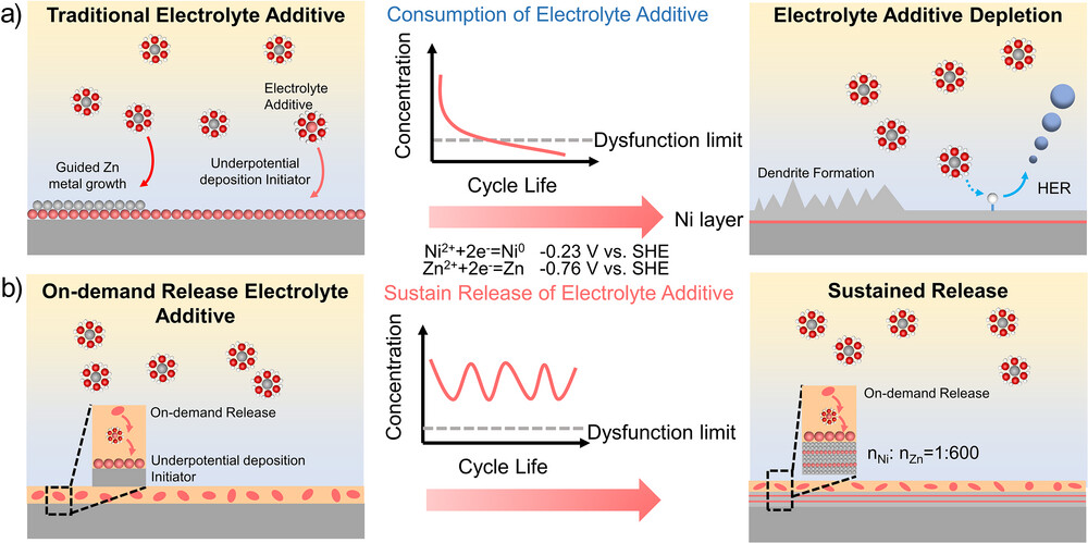
Figure 1. Schematic diagram of a) conventional electrolyte additives and b) on-demand release electrolyte additives.
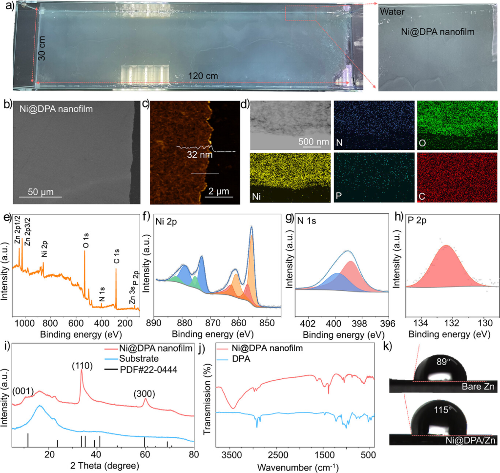
Figure 1. a) Photograph of a wafer-scale Ni@DPA nanomembrane (120 cm × 30 cm) fully floating on the air-water interface after ion-beam epitaxy. b) SEM image and c) AFM image of the Ni@DPA nanomembrane. d) TEM image showing elemental maps of N, O, Ni, P, and C. e) XPS spectrum of the Ni@DPA nanomembrane; high-resolution f) Ni 2p, g) N 1s, and h) P 2p spectra. i) XRD pattern and j) FTIR spectrum of the Ni@DPA nanomembrane. k) Static contact angle measurements on bare Zn and Ni@DPA/Zn using a 2 M ZnSO₄ aqueous electrolyte.
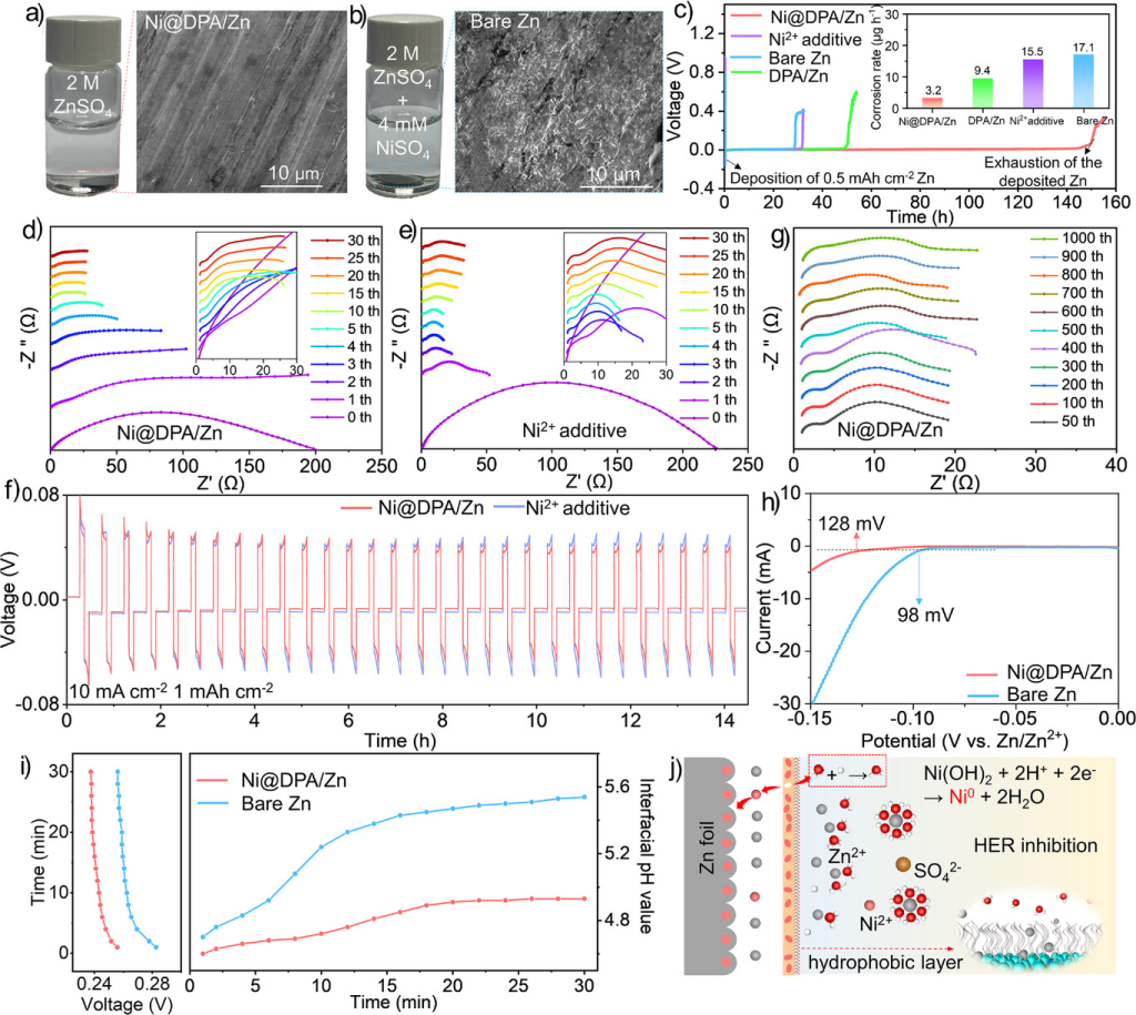
Figure 2. a) SEM image of Ni@DPA/Zn after 30 min immersion in 2 M ZnSO₄. b) SEM image of bare Zn after 30 min immersion in 2 M ZnSO₄ + 4 mM NiSO₄. c) Voltage-time curves of Zn||Zn@Cu batteries assembled with different electrodes and corresponding calculated Zn corrosion rates. d) In situ EIS curves of Ni@DPA/Zn symmetric cells in 2 M ZnSO₄. e) In situ EIS curves of bare Zn symmetric cells in 2 M ZnSO₄ + 4 mM NiSO₄. f) Voltage-time curves of the Ni@DPA/Zn symmetric cell in 2 M ZnSO₄ and the bare Zn symmetric cell in 2 M ZnSO₄ + 4 mM NiSO₄. g) Non-in situ EIS measurements of the Ni@DPA/Zn symmetric cell after long-term cycling (10 and 1 mA cm⁻²). h) Linear sweep voltammetry of Ni@DPA/Zn and bare Zn electrodes in 1 M Na₂SO₄ electrolyte. i) In situ pH changes in the anode region of Ni@DPA/Zn and bare Zn symmetric cells operating at 10 mA cm⁻². j) Schematic of Zn deposition behavior on Ni@DPA/Zn.
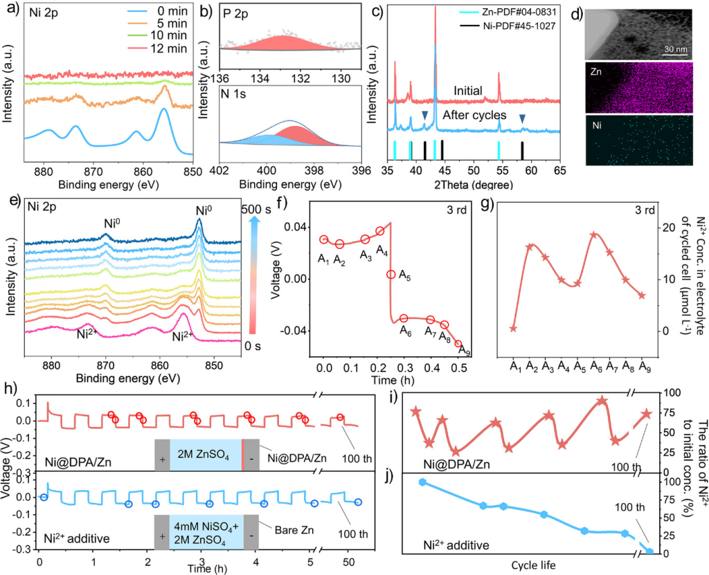
Figure 3. a) Ni 2p XPS of the Ni@DPA/Zn electrode after different Zn deposition times at 10 mA cm−2. b) P 2p and N 1s XPS of the cycled Ni@DPA/Zn electrode. c) XRD of the cycled Ni@DPA/Zn electrode (20 cycles, 20 mA cm−2, 10 mAh cm−2). d) TEM-EDS image of the cycled Ni@DPA/Zn electrode. e) XPS depth profiles of the cycled Ni@DPA/Zn electrode (10 mA cm⁻², 0.07 mAh cm⁻²) after different Ar⁺ sputtering durations. f) and g) Time-voltage curve and ICP measurement of Ni²⁺ concentration in the electrolyte during cycling (10 mA cm⁻², 2.5 mAh cm⁻²). h) Time-voltage curve recorded during electrochemical testing correlated with ICP measurements (10 mA cm⁻², 2.5 mAh cm⁻²). i) Molar ratio of Ni²⁺ to total Ni²⁺ in the electrolyte during different cycling processes of the Ni@DPA/Zn electrode, determined by ICP. j) Molar ratio of Ni²⁺ to total Ni²⁺ in the electrolyte during different cycling processes of the bare Zn electrode with added Ni²⁺, determined by ICP.
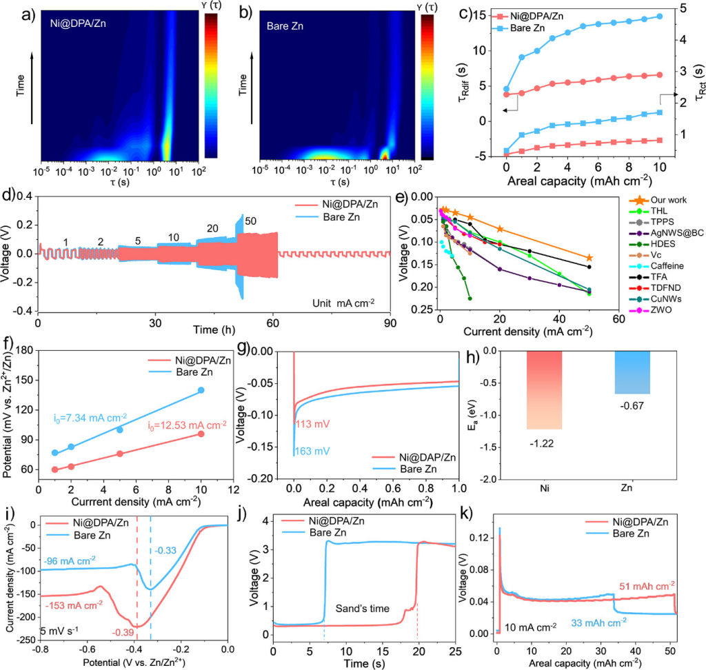
Figure 4. a) DRT data calculated from in situ EIS measurements in a symmetric cell after Ni@DPA/Zn and b) bare Zn electrodeplating at a current density of 10 mA cm−2. c) Comparison of relaxation time (τ) variations for different interfacial processes. d) Rate performance of the symmetric cell at current densities ranging from 1 to 50 mA cm−2. e) Comparison of the rate performance of the symmetric cell with previously reported anodes. [32–41] f) Exchange current densities for Ni@DPA/Zn and bare Zn. g) Voltage-capacity curves at 5 mA cm−2. h) Adsorption energies between zinc atoms and different metals. i) Limit current tests for different electrodes. j) Voltage-time curves of symmetric cells at a constant current density of 200 mA cm−2. k) Maximum plating capacities of bare Zn and Ni@DPA/Zn in button cells at 10 mA cm−2.
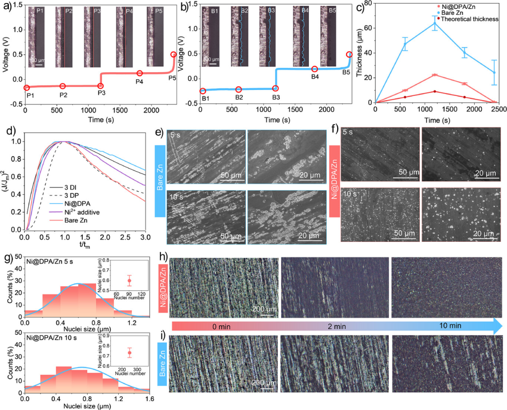
Figure 5. In situ optical microscopy images of Zn deposition/stripping on a) Ni@DPA/Cu and b) bare copper at 20 mA cm−2 (cross-section). c) Relationship between Zn thickness deposited at 20 mA cm−2 and plating/stripping time. d) Comparison of dimensionless experimental transients with theoretical 3D nucleation model. e) SEM image of Zn deposition on bare Zn and f) Ni@DPA/Zn electrode after 5 and 10 seconds of plating, along with corresponding g) histogram illustrating nucleation size (inset: relationship between statistical nucleation count and average nucleation size). h) In situ optical microscopy image of Zn deposition on Ni@DPA/Zn and i) bare Zn at 20 mA cm−2 (top view).
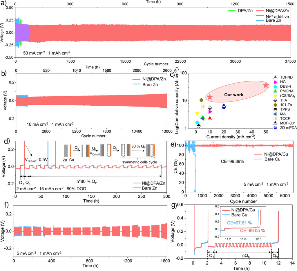
Figure 6. a) Long-term cycling performance of symmetric cells at 50 mA cm−2 and 1 mAh cm−2. b) Cycling performance of symmetric cells at 10 mA cm−2 and 1 mAh cm−2. c) Comparison of symmetric cell performance with previously reported anodes. [33, 38, 39, 44–52] d) Cycling performance of asymmetric Zn||Cu batteries at 2 mA cm^(−2) and 15 mAh cm^(−2) at 80% DOD. e) CE of Zn plating/stripping in Cu||Zn asymmetric batteries. f) Shelf recovery performance after 24-hour rest following 200 cycles at 5 mA cm⁻² and 1 mAh cm⁻². g) Average CE test using the Aurbach method (current density: 5 mA cm⁻², QT: 10 mAh cm⁻², Qc: 2.5 mAh cm⁻², n = 20).
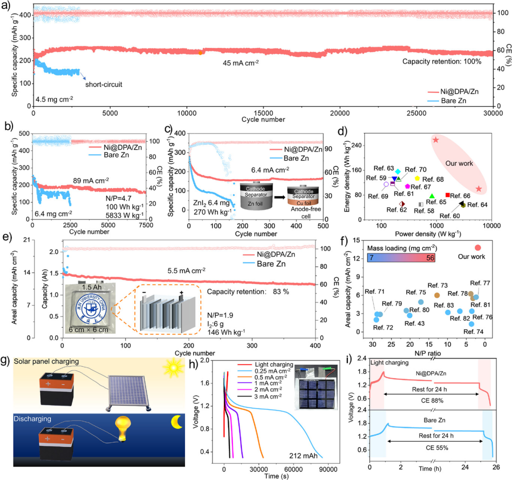
Figure 7. a) Long-term cycling performance of the Zn||I₂ full cell at 45 mA cm⁻². b) Cycling performance of the Zn||I₂ full cell at 89 mA cm⁻². c) Cycling performance of the anode-free Zn||I₂ full cell at 6.4 mA cm⁻². d) Comparison of energy and power densities with other cells. [54-66] e) Cycling performance of the Zn||I₂ pouch cell at 5.5 mA cm⁻² with an N/P ratio of 1.9. f) Comparison of the pouch cell with other cells. g) Schematic of the Zn||I₂ pouch cell charged by an external solar panel. h) Charge-discharge curves of photovoltaically charged Zn||I₂ pouch cells. i) Self-discharge curves of Ni@DPA/Zn and bare Zn cells.
Research Conclusions
This study designed an artificial SEI layer capable of continuously releasing underpotential deposition initiators, thereby overcoming the depletion of electrolyte additives during long-term operation. Composed of Ni species and DPA, this artificial SEI layer continuously supplies the underpotential deposition initiator Ni²⁺ when local pH reaches a critical point during corrosion initiation. This mechanism enables sustained release of Ni²⁺ from the artificial SEI layer, preventing depletion of electrolyte additives. Concurrently, the upper DPA layer exhibits inherent hydrophobicity, preventing direct contact between active water molecules and the electrode. This effectively suppresses corrosion and other parasitic reactions. Due to these synergistic effects, zinc-based batteries employing Ni@DPA nanolayers demonstrate outstanding cycling stability. Symmetrical cells utilizing Ni@DPA/Zn electrodes operate stably for 37,500 cycles at a high current density of 50 mA cm⁻². Similarly, the Ni@DPA/Zn||I₂ full cell retained 100% capacity after 30,000 cycles at 45 mA cm⁻². To further validate the practical potential of Ni@DPA nanolayers, an anode-less Zn-I₂ battery was assembled, achieving a high energy density of 270 Wh kg⁻¹ (based on anode and cathode active materials). Even under demanding conditions—such as high areal capacity (13.8 mAh cm−2) and low N/P ratio (1.9)—the Ni@DPA/Zn-based pouch cell retained 83% capacity after 400 cycles at ampere-hour scale. For practical application, we further demonstrated a photovoltaically charged zinc metal battery with a photovoltaic conversion efficiency of up to 10.8%. The multifunctionality of Ni@DPA nanolayers offers a promising new strategy for advancing zinc metal batteries toward more integrated energy storage applications.
Due to the limited knowledge and English level is inevitable errors and omissions, if there are errors or infringement of the text, please contact me as soon as possible by private letter, I will immediately be corrected or deleted.
Source: WeChat Battery Energy and Technology
If you do battery research or battery materials research, you might be interested in these:
Learn more about NEWARE