
Cracking the Battery Safety Puzzle: The Technological Evolution from Single Monitoring to Multidimensional Perception
Source: WeChat Official Account Smart Battery System 来自微信公众号 智能电池系统
Frequent safety accidents in lithium-ion batteries have exposed a fatal flaw in traditional Battery Management Systems (BMS): they rely solely on external electrical parameters and surface temperature monitoring, failing to perceive the true internal state of the battery. Critical early warning signals, such as internal temperature gradients, stress accumulation, and gas evolution, are often overlooked. Meanwhile, the application of fast-charging technology and high-energy-density batteries has made the internal electrochemical-thermal-mechanical-gas coupling processes even more complex. How to break through the “information barriers” of traditional monitoring and construct an intelligent monitoring system capable of “visualizing” battery internals and achieving early warnings has become an urgent scientific problem to be solved.
To address this challenge, the team of Peng Jun from the School of Automobile at Chang’an University, in collaboration with Zhu Jiangong from Tongji University and researchers from University College Dublin, published a review article in eTransportation. The study systematically integrates electrical and non-electrical parameter monitoring technologies and proposes a technological evolution route moving from “single-dimensional monitoring” to “multidimensional perception” and from “external diagnosis” to “internal visualization.” The research categorizes monitoring parameters into two major groups: electrical parameters (voltage, current, and impedance) and non-electrical parameters (temperature, deformation, and gas), providing a systematic review of various sensing technologies.

Lithium-ion batteries are widely used in portable electronic devices, electric vehicles, and energy storage systems due to their advantages, such as high power/energy density, long cycle life, and environmental friendliness. However, frequent safety accidents in recent years indicate that safety has become the greatest challenge for their large-scale application. To address this issue, the industry primarily focuses on two paths: developing safer batteries (such as Blade batteries, sodium-ion batteries, and solid-state batteries) and constructing more intelligent Battery Management Systems (BMS). Smart batteries and advanced battery management are most likely to be achieved by combining intelligent sensing technology with artificial intelligence.
Current commercial BMS only monitor external parameters (current, voltage, and surface temperature), whereas measuring internal parameters is more conducive to capturing the internal electrochemical and mechanical behaviors of the battery at the component level. Internal temperature monitoring helps in understanding heat generation mechanisms; measuring internal resistance and impedance allows for the assessment of the State of Health (SoH); and non-electrical parameters, such as volume change, mechanical stress, and gas evolution, are equally vital. The accumulation of volume change is a significant indicator of battery capacity decay, electrode stress is closely related to material cracking, and gas accumulation can lead to battery deformation or even explosion. Therefore, multi-parameter monitoring technology is essential for the precise monitoring, performance optimization, and safety management of smart batteries.
This article systematically reviews sensing methods for multi-parameter monitoring of lithium-ion batteries, categorizing measurement parameters into two major groups: electrical parameters (voltage, current, and impedance) and non-electrical parameters (temperature, deformation, and gas). This work represents the first comprehensive review of both electrical and non-electrical parameter monitoring methods. The article summarizes the working principles, experimental setups, and performance of various sensing technologies. It systematically discusses the advantages, disadvantages, and application prospects of each sensing method. Furthermore, it explores the challenges and outlook for future smart battery management from the perspectives of internal parameter monitoring and multivariable data application, providing theoretical guidance for the development of next-generation smart batteries.
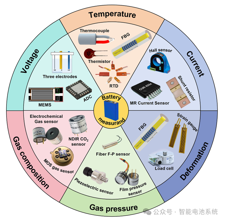
The safe and efficient operation of lithium-ion batteries involves complex electrochemical-thermal-mechanical-gas multiphysics coupling processes, and single-parameter monitoring is insufficient to comprehensively reflect the battery’s true state. As shown in Figure 1, this article systematically divides monitoring parameters into two major categories: electrical and non-electrical parameters. Electrical parameters include voltage, current, and impedance, which are the core monitoring targets of current commercial battery management systems. Non-electrical parameters cover temperature, deformation, gas pressure, and gas composition, which reveal the internal thermal behavior, mechanical degradation, and chemical evolution processes of the battery. Figure 1 illustrates the most concerned parameters of lithium-ion batteries and their corresponding sensor types, ranging from traditional electronic sensors (thermocouples, strain gauges, pressure sensors) to emerging optical sensors (Fiber Bragg Gratings, distributed fiber optic sensors) and gas analyzers (metal oxide semiconductor sensors, optical gas sensors), forming a technical framework for multi-parameter monitoring.
Voltage and Current Monitoring
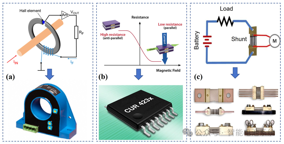
Current monitoring is a core function of battery management. Commercial battery packs primarily utilize two types of sensors: sensors based on electromagnetic effects and shunt resistors. Electromagnetic effect sensors include Hall effect sensors, magnetoresistive sensors, and magneto-optical sensors. Hall effect sensors output a voltage signal by detecting the magnetic field generated by the current; they offer the advantage of electrical isolation but require periodic calibration (see Figure 2a). Magnetoresistive sensors include three types: AMR, GMR, and TMR, with TMR sensors offering the highest sensitivity by achieving resistance modulation through changes in magnetic moment alignment (see Figure 2b). Shunt resistor sensors are connected in series within the circuit to measure current directly, offering advantages such as simple structure, low cost, and strong anti-interference capability (see Figure 2c). While these technologies are quite mature at the module level, monitoring inside individual cells remains at the research frontier. Flexible MEMS sensors developed in recent years can be implanted inside the battery to achieve synchronized monitoring of current, voltage, and temperature through micro-probe arrays (see Figure 3a), opening new avenues for in-situ internal measurement.
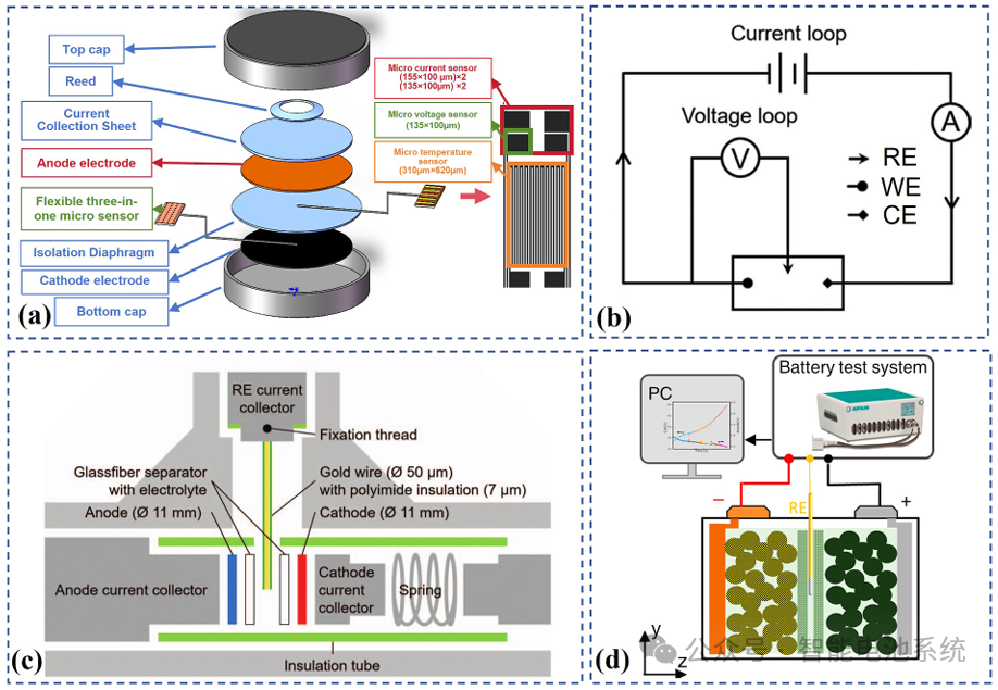
In terms of voltage monitoring, commercial batteries measure terminal voltage through integrated circuits, a technology that is now highly mature. However, external monitoring cannot obtain potential information for individual electrodes, which is crucial for understanding electrochemical reaction mechanisms and diagnosing issues such as lithium plating. Reference electrode technology has become a key tool for breaking through this limitation; as a stable electrochemical benchmark, it can separately measure the potentials of the positive and negative electrodes, providing support for electrochemical analysis. Research has shown that placing a fine insulated gold wire between the cathode and anode and alloying it with lithium in situ enables long-term impedance and potential measurements (see Figure 3c). Implanting a lithium/copper wire into commercial batteries allows for the measurement of anode potential, and studies have found that uneven lithium intercalation at the anode-separator interface can lead to excessive overpotential (see Figure 3d). Reference electrode technology not only provides a tool for understanding internal electrochemical processes but can also be used to optimize fast-charging strategies and monitor lithium plating in real time, serving as an important means of enhancing battery performance and safety.
Impedance monitoring
Battery impedance is a key parameter for evaluating state of health (SoH) and performance, influenced by multiple factors such as internal resistance, electrolyte conductivity, electrode surface area, temperature, and state of charge (SoC). Impedance measurement can be categorized into DC impedance and AC impedance based on the type of signal applied. DC internal resistance (DCIR) measurement typically employs the current pulse method, where a pulse current is applied and the resulting voltage response is recorded to calculate the impedance. Internal resistance consists of three components: ohmic resistance, charge transfer resistance, and polarization resistance.
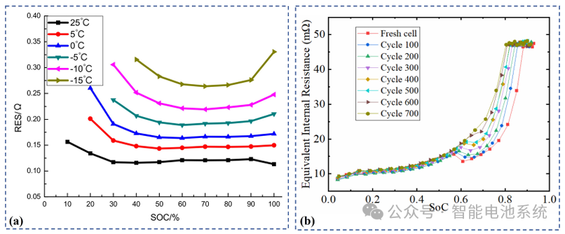
Internal resistance is significantly affected by the state of charge (SoC) and temperature. As shown in Figure 4a, the impact of temperature on internal resistance is particularly pronounced; a decrease in temperature leads to slower ion mobility and increased internal resistance, whereas the influence of SoC is relatively minor. The Hybrid Pulse Power Characterization (HPPC) test is commonly used to obtain the patterns of internal resistance variation under different conditions. Additionally, internal resistance increases as the battery ages. As shown in Figure 4b, electrode corrosion and the loss of active materials during long-term charge-discharge processes cause chemical reactions to slow down, leading to a continuous rise in internal resistance, which serves as a vital indicator for characterizing battery degradation.
Electrochemical Impedance Spectroscopy (EIS) measurement is a tool for more in-depth characterization of battery performance. Unlike DC pulses, a single-frequency input signal cannot fully characterize battery performance because charge transfer resistance is frequency-dependent. EIS measurement utilizes multi-frequency sinusoidal signals to repeat tests across a range from kHz to MHz, obtaining a complete impedance spectrum. Testing methods include galvanostatic (constant current) and potentiostatic (constant voltage) modes; the potentiostatic mode is commonly used for commercial batteries, typically applying an AC perturbation signal of 5-15 mV.
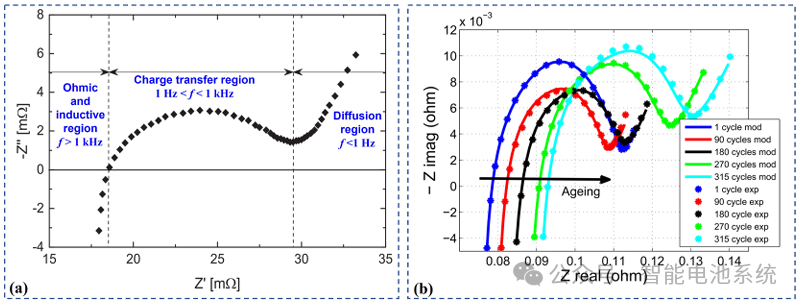
As shown in Figure 5a, in a typical Nyquist plot, the three regions of the real axis Z’ correspond to ohmic resistance, charge transfer resistance, and polarization resistance, respectively. Different frequency regions represent different electrochemical behaviors, with the high-frequency region exhibiting inductively dominant characteristics and the low-frequency region exhibiting capacitively dominant characteristics. Similar to DC internal resistance, impedance is also closely related to the state of charge, temperature, and health state. As shown in Figure 5b, the impedance spectrum changes significantly with increasing cycle count, reflecting the battery performance degradation process. Traditional measurement methods are usually implemented offline and cannot be used for real-time monitoring. To overcome this limitation, online measurement methods have emerged, using a motor controller to generate an excitation current or employing a single perturbation cycle to obtain the impedance spectrum under operating conditions. Furthermore, a reference electrode can be used to test the electrochemical impedance of the battery’s positive and negative electrodes. Studies have shown that ion contact resistance is the main factor contributing to the increase in anode impedance.
Neware battery cyclers Neware environmental chamber Neware All-in-One Battery Test Solution Neware EOL testing equipment
In current research and practical applications, electrical parameters are almost the only monitored parameters, with temperature sometimes also considered. Electrical parameters are used to estimate state of charge and state of health, which are key indicators for battery management systems to determine the battery’s available power and energy and assess its degradation state. Temperature measurement is an effective tool for battery pack thermal management. However, with the frequent occurrence of lithium-ion battery accidents in recent years, it has become clear that current battery management systems are inadequate in terms of safety management. Relying solely on electrical parameters and temperature monitoring is insufficient for fault diagnosis and early risk warning. Therefore, the monitoring of other non-electrical parameters inside the battery has received widespread attention, such as stress, volume changes, gas generation, and internal gas pressure.
Temperature Monitoring
During the operation of lithium-ion batteries, heat generation occurs throughout the entire charge-discharge cycle. Heat accumulation can lead to battery overheating, triggering electrolyte decomposition, accelerated aging, and even thermal runaway; therefore, temperature monitoring is critical for battery thermal management. Traditional electronic sensors include three categories: thermocouples, thermistors, and Platinum Resistance Temperature Detectors (RTDs).
Thermocouples operate based on the Seebeck thermoelectric effect; they offer low cost and fast response but have limited precision and are susceptible to electromagnetic interference.
Thermistors are divided into Positive Temperature Coefficient (PTC) and Negative Temperature Coefficient (NTC) types; they are characterized by fast response and small size, making them widely used in commercial battery packs.
RTDs (Platinum Resistors) provide high precision and excellent stability, often used for thermal model validation.
These sensors can be attached to the battery surface or implanted internally through miniaturization techniques to achieve in-situ monitoring. Research has shown that internal temperatures are consistently higher than surface temperatures; during 7C fast charging, the core temperature is 3.4°C higher than the surface, and the heat generation rate is 34 times that of 1C charging.
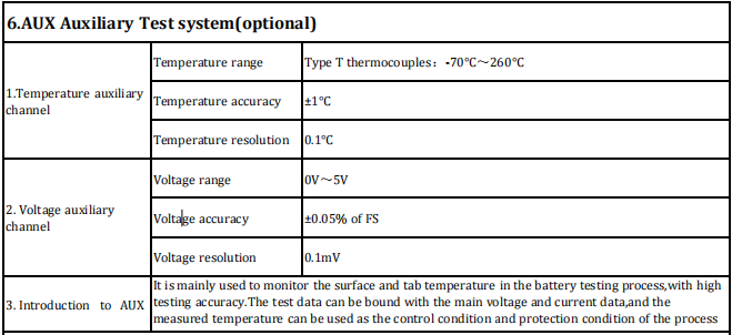
It is mainly used to monitor the surface and tab temperature in the battery testing process,with high testing accuracy.The test data can be bound with the main voltage and current data,and the measured temperature can be used as the control condition and protection condition of the process.
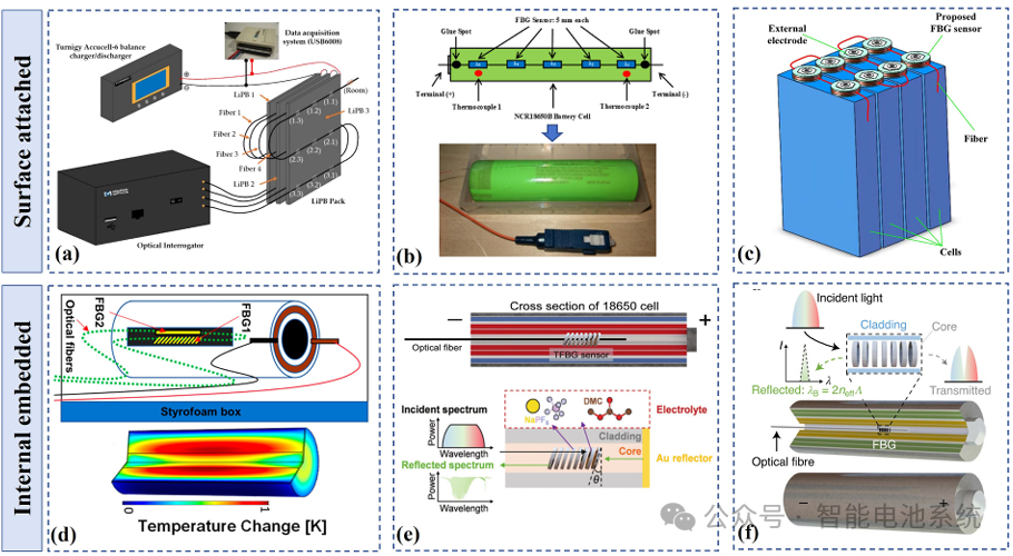
Fiber optic sensors have become a research hotspot due to their resistance to electromagnetic interference and capacity for distributed measurement. The Fiber Bragg Grating (FBG) sensor operates based on the principle of Bragg reflection, where the wavelength shifts linearly as temperature changes. FBGs possess excellent multiplexing capabilities, enabling quasi-distributed measurement; for instance, a sensing network composed of 37 FBGs can monitor the spatiotemporal thermal distribution of a battery pack containing three cells (see Figure 6a). FBGs can be implanted inside batteries to achieve operational state monitoring (see Figure 6d), and depositing a gold layer on the surface of a Tilted Fiber Bragg Grating (TFBG) allows for the monitoring of electrolyte chemical reactions (see Figure 6f).
Distributed Optical Fiber Sensors (DOFS), based on Rayleigh scattering and Optical Frequency Domain Reflectometry (OFDR) technology, offer millimeter-level spatial resolution. Standard single-mode fibers can be implanted into cylindrical batteries to achieve distributed temperature monitoring with a spatial resolution of 2.6 mm. Fibers integrated with functional electrodes have shown a capacity retention rate of 85.4% after 800 cycles at a 1C rate.
In terms of a comparison of sensing methods, electronic sensors perform single-point measurements and are susceptible to electromagnetic interference, but they are low-cost and simple to record, making them suitable for small-scale battery systems. In contrast, fiber optic sensors can monitor hundreds to tens of thousands of points using a single fiber, making them ideal for large-scale energy storage systems.
Strain monitoring
Battery strain is caused by volume changes during charge-discharge cycles, comprising both reversible and irreversible strain. Reversible volume changes originate from the expansion and contraction of electrode materials due to lithium-ion insertion/extraction, known as the “breathing effect.” Irreversible volume changes are caused by side reactions, lithium plating, and electrode structure degradation, particularly under fast-charging conditions. The cumulative volume expansion during cycling is a crucial indicator of battery capacity decay, and electrode mechanical stress is closely related to material cracking or pulverization.
Neware battery testing devices
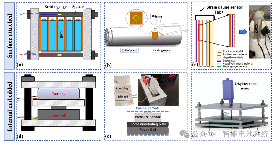
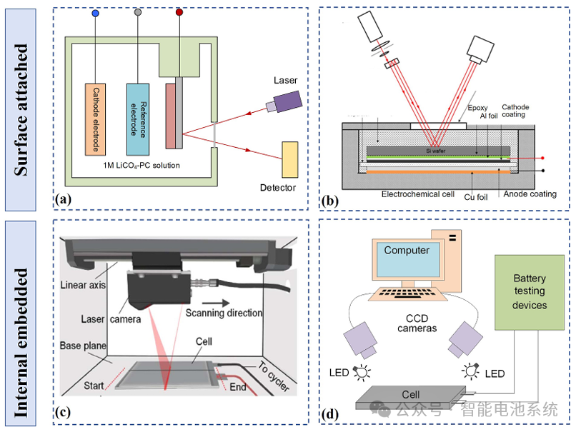
Strain gauges and force sensors are the most commonly used deformation measurement devices. Strain gauges consist of a pattern of metal foil and an insulating flexible backing. When attached to the object being measured, deformation causes changes in the size of the metal foil, thus altering the resistance. Strain gauges can be mounted on the surfaces of different types of batteries to measure deformation; for example, attaching them to the surface of cylindrical batteries to measure diameter changes shows that diameter changes are directly related to capacity loss. Thin-film strain gauges can be inserted into the winding core of 18650 batteries for in-situ stress monitoring. Experimental results show that circumferential strain is mainly dominated by the volume expansion of the negative electrode (see Figure 7c). Force sensors typically consist of a force-sensitive element and a strain gauge, and can measure battery expansion force. In pouch cells sandwiched between two parallel aluminum plates, a force sensor connected to a movable plate monitors the evolution of battery expansion force (see Figures 7d-f). Studies show that batteries with high stacking pressure exhibit shorter cycle life. Lasers and cameras provide non-contact measurement methods. Laser beam deflection (LBD) methods calculate strain and stress by measuring the deflection of reflected light as an object’s surface deforms. Multi-beam methods split the laser into multiple parallel beams captured by a CCD camera (see Figure 8b). However, these methods are complex and primarily used in laboratory research. Digital image correlation (DIC) techniques process surface images recorded by a camera using numerical algorithms. Three-dimensional DIC, using two cameras, can obtain the volume changes and strain distribution of commercial batteries (see Figure 8d).
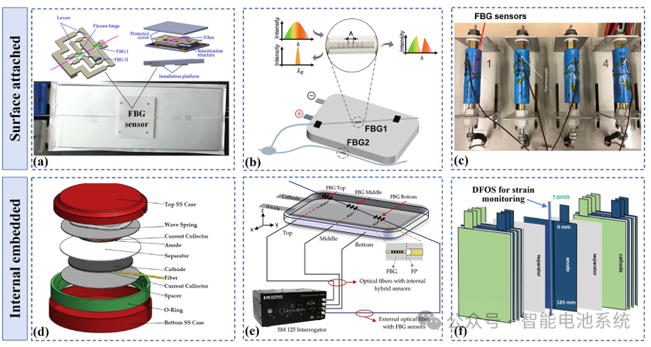
Fiber optic sensors have become a research hotspot in deformation monitoring due to their unique advantages. FBG sensors can be fixed to the battery surface to monitor strain, with studies showing that FBG responses align well with those of traditional strain gauges. To improve precision, sensitivity-enhanced FBG strain sensors using flexible hinge lever mechanisms have been developed (see Figure 9a), providing strain data that can be utilized for State of Health (SoH) estimation. FBGs can also be implanted inside batteries for in-situ monitoring, such as being embedded between the cathode and current collector of a coin cell (see Figure 9d), or within a hybrid fiber optic sensor network inside a pouch cell (see Figure 9e). Distributed fiber optic sensors can monitor the internal structural deformation of pouch cells in real time, using polytetrafluoroethylene (PTFE) tubing to decouple the cross-sensitivity between stress and temperature (see Figure 9f).
In terms of a comparison of sensing methods, strain gauges are low-cost and highly adaptable but susceptible to electromagnetic interference. Force sensors are relatively large and require clamping devices. Laser and camera-based methods offer high precision but involve complex systems and are primarily used in laboratory settings.
Although fiber optic sensors require complex demodulation, their strong multiplexing capabilities enable multi-point synchronized monitoring in large-scale energy storage systems. While deformation monitoring has not yet been implemented in mainstream commercial battery applications, it is critical for the development of battery management methods based on multi-source information fusion.
Strain gauges may be the first devices adopted for electric vehicles, whereas distributed fiber optic sensors are expected to demonstrate significant advantages in large-scale systems.
More: Highly recommend reading the full article. Enhancing lithium-ion battery monitoring: A critical review of diverse sensing approaches