
How to assemble a solid state battery mold?
1. For Reference Only
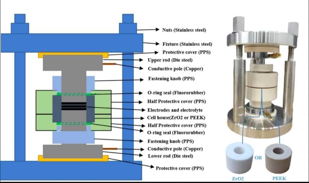
Maximum Compressive Capacity: 5T (5 metric tons).
Internal Sleeve Material: ZrO2 (Zirconia) or PEEK (Polyether ether ketone).
Internal Die and Insulating Sheet Material: PPS (Polyphenylene sulfide).
Upper and Lower Electrode Rod Material: 4Cr13 Mold Steel.
External Fixture Material: SUS304 Stainless Steel.
Electrode Rod Surface Finish: Mirror-polished.
Other Processes: Including but not limited to quenching, cryogenic treatment, chamfering, etc.
Internal Sleeve Diameter: 10 mm (other specifications customizable).
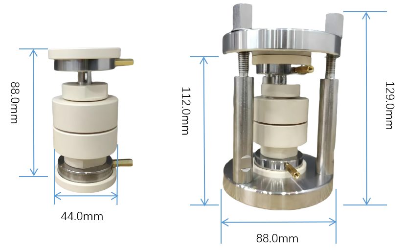
Internal Die Dimensions: Φ44*88mm.
External Fixture Dimensions: Φ88*129mm.
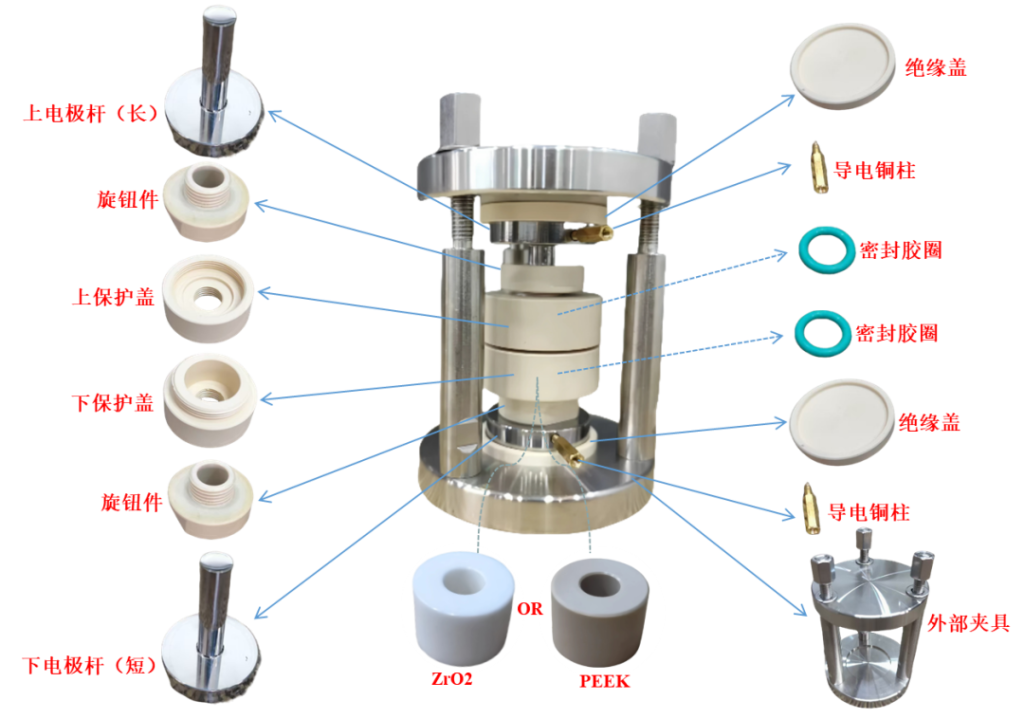
2. Structural Component Description
3. Mold battery assembly (inside the glove box)
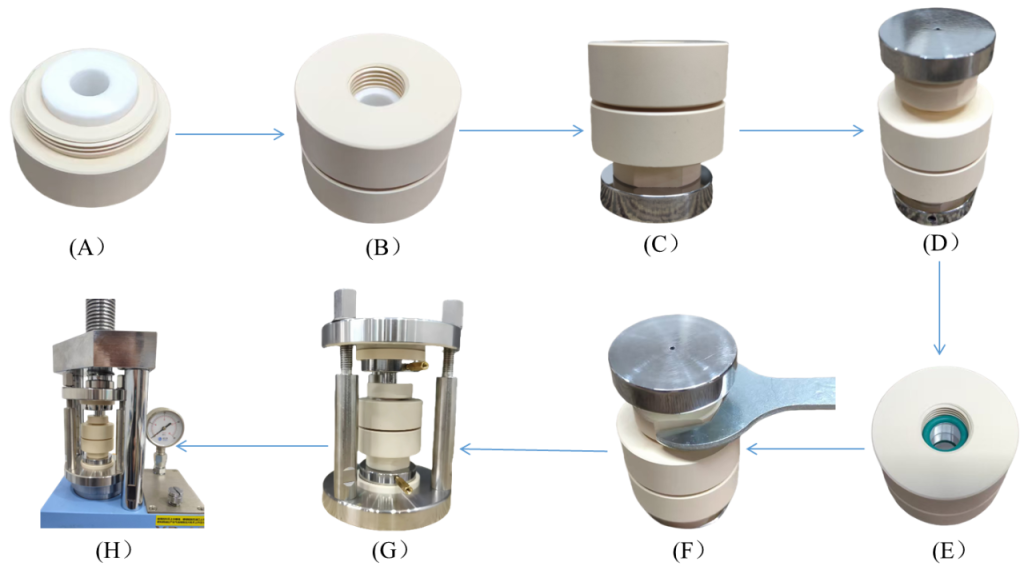
Assembly & Operation Instructions
A: Place the ceramic sleeve into the lower protective cover of the mold.
B: Align the upper and lower protective covers and screw them together to form the sample preparation cavity.
C: Insert the lower electrode rod and its corresponding screw-fastener.
D: Insert the upper electrode rod and its screw-fastener. Using a laboratory press, sequentially stack and assemble the anode, electrolyte, and cathode within the cavity.
E: Place sealing O-rings into the upper and lower recessed grooves.
F: Tighten the screw-fasteners with a wrench to achieve an airtight sealing effect.
G: Install the insulation covers and conductive copper pillars, then place the assembled mold unit into the external fixture.
H: Place the fully assembled mold battery into the press equipment, apply the required pressure, and tighten the nuts.
Finally, remove the mold battery from the glovebox and connect it to the battery testing equipment to conduct electrochemical performance tests under specific pressure. (Before removal, you may tighten the screw-fasteners again with a wrench to reinforce the seal.)
4. Maintenance and Operating Precautions
Pressure Monitoring: Note the distinction between the pressure displayed on the press (MPa) and the actual pressure exerted on the mold. The correct procedure is to take the force displayed on the press (T) and divide it by the surface area of the mold’s electrode rod; this calculation yields the actual pressure applied to the mold battery.
Operating Limits: Do not exceed the maximum pressure range of the testing fixture during operation.
Inspection: Periodically inspect the upper and lower electrode rods for any signs of unevenness, surface roughness, or pitting.
Source: WeChat Official Account Battery Technology TOP+ 电池技术 TOP+
Neware battery cyclers for solid state batteries, solid state battery mold, Neware all in one for solid state batteries, contact us! Neware
Due to the limited knowledge and English level is inevitable errors and omissions, if there are errors or infringement of the text, please contact me as soon as possible by private letter, I will immediately be corrected or deleted.