
How to charging and discharging your Solid-State Batteries?
Source: WeChat Official Account “Learn Batteries Together” 来源于微信公众号 一起学电池
Core Objective of Solid-State Battery Charge-Discharge Testing:
To charge (lithium ions de-intercalate from the cathode and intercalate into the anode) and discharge (lithium ions de-intercalate from the anode and intercalate into the cathode) the solid-state battery under controlled conditions, while recording key parameters such as voltage, current, time, and temperature.
Key Prerequisites for Solid-State Battery Charge-Discharge Testing:
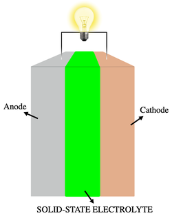
Battery Preparation: Ensure you have a fully assembled solid-state battery (coin cell, pouch cell, or cylindrical cell). This typically comprises the cathode, solid-state electrolyte (SSE), anode, current collectors, and the casing.
Testing Equipment: A battery testing system (also known as a battery cycler or charge-discharge tester, e.g., NEWARE) is required to precisely control current/voltage and log data.
Environmental Control: It is best to conduct tests within an isothermal chamber (environmental chamber) to regulate temperature (commonly 25°C), as temperature significantly impacts solid-state battery performance.
Pressure Apparatus: Solid-state batteries require continuous, stable, and uniform external pressure to maintain high-quality electrode/electrolyte interface contact. This is the most distinct characteristic compared to liquid battery testing!
Coin Cells: Use specialized spring-loaded or bolt-type fixtures to apply fixed pressure (typical range: 1 MPa to several hundred MPa, depending on the research system).
Pouch/Cylindrical Cells: Use pressure jigs equipped with load cells or pneumatic/hydraulic presses to maintain constant pressure throughout the testing process.
Detailed Testing Procedure for Solid-State Battery Charge-Discharge:
Phase I: Preparation and Connection
1. Equipment Inspection and Calibration:
Check that the battery testing system, isothermal chamber, and pressure apparatus are functioning correctly.
Calibrate the voltage and current sensors of the testing system (if supported or required by the periodic maintenance schedule).
2. Environmental Setup:
Set the isothermal chamber to the target testing temperature (e.g., 25°C) and wait for the temperature to stabilize. Neware temperature chamber
3. Battery Installation and Pressure Application:
Coin Cells: Carefully place the assembled coin cell into the fixture. Tighten the screws (e.g., using a torque wrench) or install the spring fixture as required to ensure the design pressure is applied. Record the applied pressure value.
Pouch/Cylindrical Cells: Place the battery into the pressure jig. Adjust the jig or press to apply the preset constant pressure. Ensure the pressure sensor reading remains stable at the target value.
4. Connecting Test Leads:
Connect the battery’s positive and negative terminals to the corresponding channels on the tester using the leads. Ensure correct polarity! (Red lead to positive, black/blue lead to negative). Reversing the polarity may damage the battery or the equipment.
Verify that all connections are secure to avoid contact resistance or intermittent signals.
5. Parameter Configuration (via Software):
Channel Selection: Select the specific testing channel where the battery is connected.
Battery Information: Enter an identifier (e.g., Battery ID/Batch Number).
Core Test Parameters:
Charge Mode: CC-CV (Constant Current-Constant Voltage, most common), CC (Constant Current), or CP (Constant Power).
Discharge Mode: CC (Constant Current, most common), CP (Constant Power), or CR (Constant Resistance).
Voltage Limits:
Charge Cut-off Voltage ($V_{max}$): The maximum allowable voltage (e.g., 4.2V or 4.3V for NMC622/Li systems).
Discharge Cut-off Voltage ($V_{min}$): The minimum allowable voltage (e.g., 3.0V or 2.5V). Incorrect settings may lead to irreversible battery damage.
Current/C-rate:
Charge Current ($I_{charge}$): Calculated based on battery capacity. For a 1 mAh battery, a 0.1C rate equals a 0.1 mA current. Initial rates are typically 0.1C or 0.2C.
Discharge Current ($I_{discharge}$): Also set based on capacity/C-rate; may be identical to or different from the charge current.
CC to CV Transition Criteria (CC-CV mode only): Terminate charging when the current drops to a specific threshold (e.g., 0.05C) or a time limit is reached.
Cycle Settings: Define one full charge/discharge as one cycle; set total cycles (e.g., 50, 100).
Rest Time: Set a rest period (e.g., 5–30 mins) before the test or between steps to allow the internal state to reach equilibrium.
Data Logging Interval: Set the frequency for recording voltage, current, time, and capacity (e.g., every 1s or every 10mV change).
Naming and Saving: Name the testing protocol and save the configuration.
Phase II: Executing the Test of Solid-State Batteries
1. Pre-test Rest Period (OCV Period)
Start the test program in the software. The initial step is typically a rest period (e.g., 10–30 minutes) to record the Open Circuit Voltage (OCV).
2. The Formation Cycle (First Cycle)
First Charge: The system performs the initial charge according to the set mode (usually CC-CV). A lower current (e.g., 0.05C or 0.1C) is often used to facilitate the formation of stable SEI/CEI layers (Solid/Cathode Electrolyte Interphase), which are necessary even in solid-state systems. Monitor the voltage curve closely for any irregularities.
First Rest: Allow the battery to rest after the charge is complete.
First Discharge: The system discharges the battery to the cut-off voltage using the set mode (usually CC). Record the initial discharge capacity, which is often regarded as the battery’s nominal capacity.
Post-Discharge Rest: Another rest period follows the discharge.
3. Subsequent Cycling
The system automatically repeats the programmed steps (Charge → Rest → Discharge → Rest) until the target number of cycles is reached.
Pressure Monitoring: Continuously monitor pressure stability. For pouch or cylindrical cells with sensors, log the pressure values; for coin cells, ensure the fixtures remain tight.
Real-time Monitoring: Observe the live voltage and current curves in the software. Look for voltage dips, plateau anomalies, or “noisy” data that might indicate internal short circuits or poor contact.
4. Process Supervision & Safety
Regularly inspect equipment operation, chamber temperature, and pressure readings.
Safety Alerts: Stay alert for abnormal sounds, odors, smoke, or a rapid spike in battery temperature. (An Infrared (IR) thermometer can be used to monitor the cell surface temperature). If any anomaly occurs, terminate the test immediately.
Phase III: Test Conclusion and Data Analysis your Solid-State Batteries
1. Test Termination
The test stops automatically or manually when the preset number of cycles is reached or if a safety trigger (e.g., voltage/temperature out-of-bounds) is activated.
Ensure the battery completes the test in a rest state.
2. Disassembly and Safety Handling
Disconnect the tester leads from the battery first.
Carefully release the pressure apparatus (exercise caution with high-pressure fixtures).
Remove the battery. For batteries with an unknown post-test state, store them in an explosion-proof container.
Clean the workstation.
3. Data Exporting
Export the raw data from the software (typically in
.csvor.txtformats). The dataset should include columns for time, voltage, current, capacity, cycle number, and step status (Charge/Discharge/Rest).
4. Data Analysis (Using tools like Origin, Python, or Excel)
Charge-Discharge Curves: Plot Voltage vs. Capacity curves. Observe the charge/discharge voltage plateaus, the magnitude of polarization, and the length of the plateaus.
Capacity: Calculate the charge and discharge capacity for each cycle. Plot Capacity Retention (Discharge Capacity at Cycle N / Initial Discharge Capacity) vs. Cycle Number to evaluate cycling stability.
Coulombic Efficiency (CE): Calculate the CE for each cycle:

An ideal value is close to 100%; a decline indicates side reactions or lithium loss. Plot CE vs. Cycle Number.
Energy Efficiency: Evaluate total energy loss using:

Rate Capability (Optional): If different C-rates were tested (e.g., 0.1C, 0.2C, 0.5C, 1C), plot the capacity retention or voltage curves at these rates to assess high-power performance.
Failure Mode Analysis: Observe degradation trends (linear vs. “capacity dive”), CE fluctuations, and increasing voltage polarization. Use changes in the curve shape to infer failure mechanisms such as interfacial degradation, lithium dendrite growth, contact loss, or structural breakdown of materials.
Comparative Analysis: Compare results across different pressures, temperatures, or material systems to determine optimal conditions.


Critical Considerations for Solid-State Batteries:
Pressure as a Key Variable: Insufficient pressure leads to poor interfacial contact, increased internal resistance, and a sharp drop in capacity (or total failure). Conversely, excessive pressure may crush brittle electrolytes. You must specify the applied pressure value when reporting results! Exploring the optimal pressure range is often a primary goal of the research.
Pressure Uniformity: Ensure the fixture design applies pressure uniformly across the active area of the battery to avoid local stress concentrations.
Interfacial Stability: The compatibility between the solid-state electrolyte and the electrodes is critical. Anomalies observed during testing may stem from interfacial reactions or contact failure.
Current Density: Solid-state ionic conductivity is generally lower than that of liquid electrolytes, leading to higher polarization at high C-rates. When selecting a C-rate, consider the battery’s actual power capability.
Lithium Metal Anode: If using a lithium metal anode, pay close attention to lithium dendrite growth and volume changes. Tiny fluctuations in the low-voltage plateau (near 0V vs Li+/Li) may suggest the formation of dendrites.
Due to the limited knowledge and English level is inevitable errors and omissions, if there are errors or infringement of the text, please contact me as soon as possible by private letter, I will immediately be corrected or deleted.