
Coin Cells: From Electrode Preparation to Performance Testing (1)
The Importance of Coin Cell Assembly in Lithium-Ion Battery Development
In the early stages of research and development, as well as production, lithium-ion battery materials need to be tested for their electrochemical performance through the assembly of coin cells. This article summarizes previous literature and combines practical experience to introduce methods for assembling laboratory lithium-ion coin cells.
The development of any new battery material typically goes through five stages: laboratory research, pilot-scale testing, medium-scale testing, scale-up, and commercial application. The laboratory research stage is essential for testing material performance, validation, and value assessment. Laboratory measurement data not only holds significant scientific value but also helps determine whether certain materials and battery systems have practical application value and commercial potential in the early stages of development. Laboratory coin cells are used not only to test the performance of existing materials but also to conduct preliminary electrochemical performance tests and evaluations of new materials and processes. Proper assembly of coin cells is of great significance for the development, preparation, and full-cell design and application of these materials.
Electrode Preparation: Material Selection and Weighing
The cathode and anode materials used in laboratories are often purchased, but they can also be prepared experimentally. The active materials for cathodes and anodes are generally powders, with particle sizes that should not be too large to ensure uniform coating. Large particles can limit test results due to material kinetics and cause non-uniformity in the electrode sheets. For laboratory research, the maximum particle diameter (Dmax) of cathode and anode materials generally does not exceed 50 μm, while for industrial lithium battery materials, Dmax is typically less than 30 μm. Large particles, agglomerates, or nano-sized materials are often treated by sieving or grinding. Common conductive agents used in lithium batteries include carbon-based materials, such as acetylene black (AB), conductive carbon black, Super P, and 350G. Common binder systems include polyvinylidene fluoride (PVDF) in an oil-based system and polytetrafluoroethylene (PTFE) in an aqueous system (usually in the form of an emulsion), as well as styrene-butadiene rubber (SBR) emulsion. NMP (N-methylpyrrolidone) is commonly used as an oil-based solvent.
When preparing electrodes in the laboratory, the mixing ratio and steps vary depending on the test materials and mixing processes. For example, in common graphite anode electrodes, the content of CMC (carboxymethyl cellulose sodium) is generally less than 10%, the content of SBR is less than 10%, and the content of conductive additives is generally less than 10% (except for high-rate batteries). For silicon-based anode materials, considering their poor electrical conductivity, the binder content in the electrode is increased, and the type of conductive additive is changed. Some researchers adjust the proportion of CMC to 20% and SBR to 20%, and add carbon nanotubes (CNT) to the conductive additives. For high-power battery electrode research and testing, the content of conductive agents is often increased to about 20%. High binder and conductive additive ratios are used to fully demonstrate the electrochemical characteristics of the active materials of the cathode and anode. However, in actual lithium-ion batteries, the binder mass ratio in the electrode is often around 2%, and the conductive additive ratio is usually between 1% and 2%.
The weighing accuracy for lithium-ion battery materials should not be lower than 1% of the weighing mass using an electronic balance to avoid significant weighing errors. The active materials and conductive agents can be weighed directly as powders, while the binder is weighed by first weighing the powder and then mixing it with a certain amount of solvent to prepare the binder solution (e.g., PVDF dissolved in NMP at a dissolution ratio of 10% by mass), and then calculating the solid binder content based on the actual volume added.
Current Collector Selection
The current collectors for the cathode and anode electrodes of lithium-ion batteries are aluminum foil and copper foil, respectively. If single-sided smooth foil is used, coating is often done on the rough side to enhance the bonding between the current collector and the material. There is no strict requirement for the thickness of the foil, but the uniformity of the foil’s areal density is highly important. For silicon-based anode materials, carbon-coated copper foil is generally used to improve adhesion, reduce contact resistance, and enhance the reproducibility of the test results and charge-discharge cycle performance.
Electrode Coating and Preparation Process
The laboratory electrode preparation process generally includes two steps: mixing and coating. The mixing process can be done manually or mechanically, while the coating process can be done manually or using a small coating machine. When mixing, the method is chosen based on the amount of material. For example, when the mass of the active material is between 0.1 and 5.0 grams, manual grinding is recommended. When the mass of the active material exceeds 5.0 grams, a mixer should be used. Since the amount of paste prepared each time in the laboratory is limited, manual coating is often used. When there is enough paste, a small coating machine can be used. The entire electrode preparation process must be carried out in a dry environment, and all materials and equipment must be kept dry.
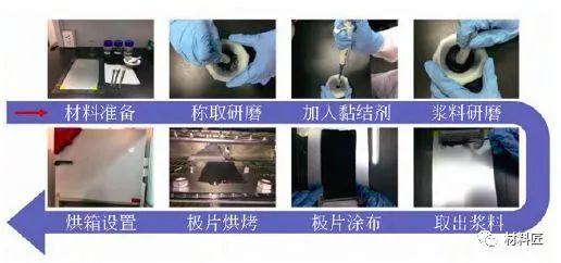
Figure 1: Manual Mixing and Coating Process
Figure 1 illustrates the process of preparing electrodes using manual mixing and coating methods. This process includes several steps: initial material preparation, weighing and grinding of active materials and conductive agents, adding binders, grinding the slurry, manually coating the electrodes, and drying the electrodes. In contrast, the mechanical mixing process involves material preparation, equipment setup, preparing the binder slurry, adding conductive additives, configuring the slurry, adding electrode materials to the slurry, coating, and drying the electrodes (Figure 2). It is important to note that the binder (such as PVDF) should be dissolved in the solvent NMP at a temperature below 50°C and stirred until completely dissolved. Then, the slurry is prepared according to the ratio. During the mixing process, any material stuck to the walls should be removed and mixed into the slurry to avoid deviations in the material ratio. The mixing time should neither be too short nor too long, and the slurry should be uniform but not too fine. These factors can affect the overall quality and uniformity of the electrode and directly impact the electrochemical performance of the material and its evaluation.
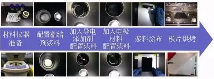
Figure 2: Mechanical Mixing and Manual Coating Process
It is particularly important to note that the areal capacity of electrodes is generally set to 2–4 mA·h/cm², with a minimum not recommended below 1 mA·h/cm². This loading level of active material is closer to that of industrial applications, facilitating accurate evaluation of the material’s rate and low-temperature characteristics. In some cases, the loading can exceed this value, such as in research on thick electrodes. However, electrodes with lower areal capacity have several issues: on one hand, the weighing error is larger; on the other hand, due to the thin electrode, the kinetic performance is better, the volume change is smaller, and the electrolyte is relatively excessive. This makes it easier to measure the highest capacity of the material, but the rate and cycle performance measured in half-cells may be significantly higher than those under actual full-cell operating conditions. Therefore, the kinetic and cycle performance data obtained under these conditions may not correspond well with large-capacity actual batteries. Of course, even if the system requirements are different, comparing the performance of materials under the same electrode preparation conditions still has some significance. However, comparing kinetic and cycle performance data obtained under different electrode preparation conditions often has low reliability, and the consistency of manually made thin electrodes in the laboratory is often difficult to ensure.
Electrode Drying Conditions, Rolling Process, Punching, and Weighing
Electrode drying generally needs to consider three factors: drying temperature, drying time, and drying environment. For oil-based NMP, the drying temperature needs to be above 100°C. Under the premise of being able to dry, the drying temperature should be reduced as much as possible, and the drying time should be increased. For some materials that are easily oxidized or unstable in high-temperature air, drying should be carried out in an inert atmosphere drying box. The moisture content of the electrode can also be directly measured to determine the drying conditions. During the electrode rolling process, the electrode needs to be compacted, and the compaction density should be as close as possible to the compaction density of industrial electrodes. To measure the kinetic limit of the material, the compaction density can be adjusted according to the research purpose. After preparing the electrodes, place them between weighing papers and put them into a pressing machine to punch out small electrodes (Figure 3). The diameter of the small electrodes can be adjusted according to the size of the punch mold of the pressing machine. The laboratory commonly uses a punch mold with a diameter of 14 mm (corresponding to the CR2032 coin cell). The quality of the punched small electrodes should be evaluated, and electrodes with regular shapes and smooth surfaces and edges should be selected. If the edges of the electrodes have burrs or material lifting, they can be slightly treated with a small brush. The number of small electrodes prepared by punching should be adjusted according to the test requirements and the coating area, and the number of electrodes used for charge-discharge testing should be no less than 5 (it is recommended to select more than 8 complete test electrodes).
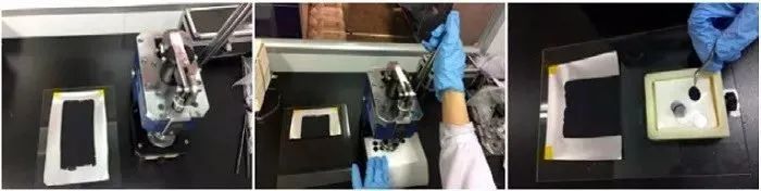
Figure 3: Manual Punching Process of Electrodes
After selecting the qualified small electrodes, they are moved to a high-precision balance (with an accuracy no lower than 0.01 mg) for weighing. The weighed electrodes are then placed into bags for battery assembly, and the corresponding data are recorded (Figure 4). In addition to weighing the electrodes, the thickness of the electrodes is measured using a thickness gauge. If the measurement errors of multiple electrodes are within 3%, the uniformity of the electrode thickness is considered good, and the average thickness value is recorded.
Due to the limited level of knowledge inevitably errors and omissions, if there are errors or infringements in the text, please contact me as soon as possible by private letter, I will immediately make corrections or deletions.

Figure 4: Weighing and Marking of Punched Electrodes
After weighing the electrodes, they are placed into a vacuum drying chamber. The chamber is evacuated to 0.1 MPa, and the drying temperature and time are set. A drying regimen of 120°C for 6 hours can be used to further remove moisture from the electrodes. It is recommended to label the experimental information after starting the heating process to prevent accidental operations by others (Figure 5).
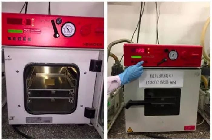
Figure 5: Electrode Drying and Baking Process
Double-Sided Electrode Processing Methods
In laboratory testing and analysis, it is also necessary to analyze and evaluate the electrochemical performance of electrodes prepared on industrial production lines and electrodes removed from battery cells. These electrodes are often double-sided coated electrodes. Therefore, before assembling coin cells for testing, double-sided electrodes need to be processed into single-sided electrodes (exposing the current collector). Common processing methods include the scalpel method, wiping method, and backside adhesive method.
Scalpel Method: This method involves using a surgical scalpel to scrape one side of the target electrode. It can be operated directly inside a glove box. However, this method is prone to damaging the current collector and is time-consuming, so it is not recommended.
Wiping Method: This method requires using water as a solvent to wipe one side of the negative electrode or NMP (N-methylpyrrolidone) for the positive electrode. After wiping until no obvious active material is visible on the back (visual inspection is sufficient), the electrode is punched into standard-sized single-sided electrodes using a punching machine. This method is simple to operate but is susceptible to solvent or atmosphere penetration, which can affect the other side of the electrode. Additionally, it is difficult to prepare samples from the edges of the electrode, and it is mostly used for the central area of the electrode.
Backside Adhesive Method: This is a double-sided electrode processing method recently developed by the failure analysis team at the Institute of Physics, Chinese Academy of Sciences (referred to as the Institute of Physics). It involves folding the edges and applying conductive adhesive to the backside, encapsulating the backside of the target electrode within the current collector and conductive adhesive to form a single-sided electrode. This method is easy to operate and allows for sampling at any location on the double-sided electrode to create single-sided electrodes, all of which can be completed inside a glove box.
After single-sided processing, the target electrode samples need to be cleaned to remove lithium salts and residual electrolyte from the electrode surface. A common method is to soak the single-sided electrode in a solvent like DMC for 6–8 hours, or use tweezers to hold the electrode and a pipette or dropper to rinse the active material side of the electrode with DMC several times, or a combination of both methods. After cleaning, the electrode is placed in a vacuum chamber for vacuum drying to remove the solvent. Both cleaning and vacuum drying are conducted inside a glove box. After drying, the electrode can be placed in a flat mold to maintain its flatness for subsequent coin cell assembly.
Due to the limited knowledge and English level is inevitable errors and omissions, if there are errors or infringement of the text, please contact me as soon as possible by private letter, I will immediately be corrected or deleted.
Learn more about NEWARE
Coin Cells: From Electrode Preparation to Performance Testing (2)
Coin Cells: From Electrode Preparation to Performance Testing (3)
Source: WeChat https://mp.weixin.qq.com/s/Fs2wgoa5PqkSomC9StTS1Q