
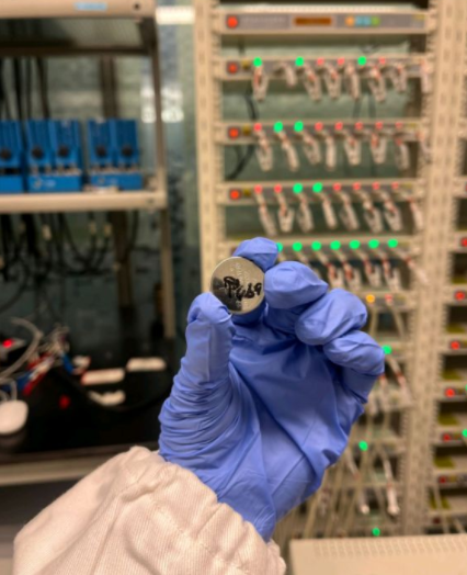
Coin Cells: From Electrode Preparation to Performance Testing (2)
Precautions in Laboratory Coin Cell Assembly
Selection and Treatment of Lithium Metal, Separator, and Electrolyte
Laboratory-grade lithium metal sheets provide a significantly excessive amount of lithium source (1 mA·h/cm² is equivalent to a 5 μm thick lithium foil, while commercially available lithium sheets are typically 400–500 μm thick, equivalent to 80–100 mA·h/cm². Industrial-grade electrodes usually have a single-sided capacity of 2–4 mA·h/cm²). These sheets have minimal impurities and must be larger in size than the electrodes to be tested. Lithium sheets can be directly purchased from relevant companies or suppliers under inert atmosphere protection and should be disassembled and used within an inert atmosphere glove box. The purity of the lithium sheet should be no less than 99.9%. For assembling coin half-cells, lithium sheets with a diameter of 15–15.8 mm (corresponding to a 14 mm electrode for CR2032 coin cells) and a thickness of 0.5–0.8 mm are commonly used. The surface of the lithium sheet should be flat, bright silver, and free from oil stains, holes, and tears.
The type of separator should be selected based on experimental requirements. It is generally an insulating membrane with nanoscale pores that allows for bidirectional ion transport after absorbing the electrolyte. Commonly used separators are single or multilayer polyethylene or polypropylene membranes. Commercial separators are usually purchased and punched into regular circular shapes using a punch machine. The diameter of the separator should be larger than that of the lithium sheet and the electrode to be tested, typically matching the inner diameter of the coin cell case (e.g., for CR2032 cells, the separator diameter is 15.5–16.5 mm). In the laboratory, industrial-grade polypropylene membranes such as Celgard 2400 or Celgard 2500 are commonly used.
When assembling laboratory coin lithium-ion batteries, a LiPF₆-based electrolyte system is usually chosen [for example, the electrolyte for lithium iron phosphate batteries is typically a 1 mol/L LiPF₆ solution with a 1:1 (volume ratio) mixture of EC/DEC as the solvent]. The electrolyte can be selected according to experimental requirements, such as standard ratio electrolytes or those containing specific additives. The amount of electrolyte used in coin cell assembly is usually excessive. For example, in CR2032 coin cells, the electrolyte volume is generally 100–150 μL, while in simulated cells, it is typically 200 μL. For long-cycle testing, the amount of electrolyte can be appropriately increased.
Selection of Electrodes and Cells
Electrodes that have been prepared should have a smooth surface without any large particles. If there is no significant material loss during drying, cooling to room temperature, and transfer, it can be preliminarily determined that the electrode preparation is qualified. Further judgment can be made by comparing the mass, thickness, and the degree of material loss at the edges of the punched electrodes. If there are significant differences in mass and thickness, and the edges of the electrode discs have varying degrees of material loss, it indicates that the electrode preparation is not qualified. Electrodes with uniform mass, thickness, and edge material loss should be selected for assembling cells for testing.
Coin cells and simulated cells that have been prepared should have a flat and undamaged shell mold, with no signs of corrosion or obvious leakage. Using a multimeter or a battery tester to measure the open-circuit voltage of the prepared cells, if the open-circuit voltage of the cathode material half-cell is above 3 V, and that of the anode material half-cell is within 2.5–3.5 V, it indicates that there is no obvious short circuit in the assembled cell. If the open-circuit voltage is abnormal, the assembled cell is considered unqualified. Necessary cell information should be marked on the qualified coin cell cathode shell with a marker pen.
Precautions
When using metallic lithium as the anode in a coin half-cell, the anode material in the full cell is actually the cathode in the coin cell. In the coin cell, the diameter of the separator should be greater than that of the lithium sheet, which in turn should be greater than that of the electrode. When moving the entire coin cell with tweezers, insulated tweezers should be used to prevent short circuits caused by contact between the positive and negative electrodes. To ensure the electrochemical testing projects later on and to account for errors and operational mistakes, the number of coin cells or simulated cells assembled in the laboratory with the same material should generally be no less than five. During the preparation process of coin cells and simulated cells, when placing the lithium sheet, the smooth edge of the lithium sheet should face the separator. If necessary, a flat object that does not react with lithium can be used to flatten the surface of the lithium sheet to prevent the edges of the lithium sheet from puncturing the separator and causing a short circuit. Before use, all components of coin cells and simulated cells should be cleaned. Stainless steel parts can be ultrasonically cleaned in sequence with degreasing agents, acetone, ethanol, and water. The cleaning temperature can be appropriately increased when using degreasing agents to remove oil from the surface of the parts. Polytetrafluoroethylene parts should be cleaned with reagents other than acetone. After cleaning, the parts should be dried in an oven. When assembling simulated cells and placing electrodes, it should be noted that electrodes are prone to movement and flipping. Tweezers should be used with care to avoid damaging the electrodes and causing electrolyte leakage. It is recommended to use blunt, insulated tweezers for handling.
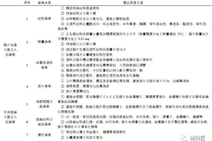
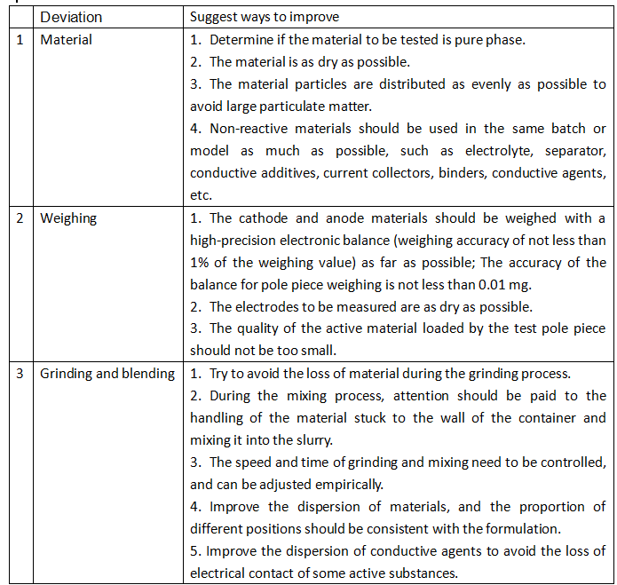
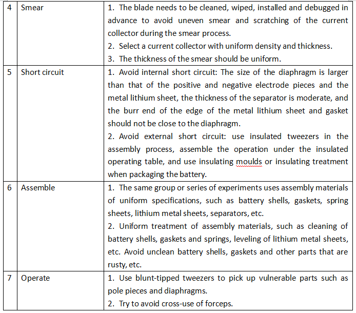
Table 1: Errors Caused by Assembly Process and Improvement Measures
I know you don’t understand Chinese, right? Here is the translation.
After the assembly of the buckle is completed, the next thing to do is the battery performance test, so what are the performance test methods of the battery? What should we pay attention to?
The charge-discharge mode of a button battery
The charge-discharge test of the button battery often uses constant current charging (CC), constant current-constant voltage charging (CC-CV), constant voltage charging (CV), and constant current discharge (DC) to test and analyze the charging and discharging behavior of the battery, and characterize the electrochemical performance parameters such as the capacity of the battery or material, the coulombic efficiency, the charge-discharge platform, and the changes in the internal parameters of the battery by analyzing the changes in the data in the process.
The stepped charge-discharge mode is mostly used to test the DC internal resistance, polarization and diffusion impedance performance. Considering the influence of the content of the active material and the size of the electrode piece on the test current, the constant current charging is often in the form of current density, such as mA/g (current per unit mass of active substance) and mA/cm2 (current per unit area of the electrode piece).
The size of the charge-discharge current is often expressed by the charge-discharge rate, that is: charge-discharge rate (C) = charge-discharge current (mA) / rated capacity (mA·h), if the battery with a rated capacity of 1000mA·h is charged and discharged with a current of 500mA, the charge-discharge rate is 0.5 C. At present, the industry standard QCT/743-2006 for lithium-ion batteries for electric vehicles has been published and used, which points out that the general charge-discharge current of lithium-ion is C/3, so the charge-discharge behavior test containing C/3 also often appears in the charge-discharge test of lithium-ion batteries in the laboratory.
Rate performance test
There are three forms of rate performance test, including using the same rate constant current and constant voltage charge, and using different rate constant current discharge tests to characterize and evaluate the performance of lithium-ion batteries at different discharge rates; Or use the same rate for constant current discharge, and use different rates of constant current charging test to characterize the charging performance of the battery at different rates; and charge and discharge using the same rate for charge and discharge test. The commonly used charge-discharge rates are 0.02C, 0.05C, 0.1C, C/3, 0.5C, 1C, 2C, 3C, 5C and 10C.
When testing the cycle performance of the battery, it is mainly necessary to determine the charging and discharging mode of the battery, cycle until the battery capacity drops to a certain specified value (usually 80% of the rated capacity), the number of charging and discharging times experienced by the battery, or compare the remaining capacity of the battery after the same cycle, so as to characterize the cycle performance of the test battery. In addition, the test environment of the battery has a certain impact on its charging and discharging performance.
Introduction to experimental instruments
Neware 0~60℃ and -70/-40/-20~150℃ temp chamber
Neware Isolate the explosion chamber
Laboratory battery explosion-proof chambers are mostly used for the testing of large-capacity batteries, and will also be used in the study of some special performance tests of button batteries, such as high C-rate, high-temperature performance tests, etc. The temperature control of the laboratory chamber is mostly 25°C, and the temperature difference between the actual temperature and the set temperature is not more than 1°C. In the high and low temperature performance test of the battery, the minimum temperature can reach 70°C, and the maximum temperature can reach 150°C. Considering that the price of the chamber with a wide temperature range is more expensive and the application is more concentrated, it is recommended that multiple chambers be set to different temperatures for centralized testing, that is, the same verification material is assembled with multiple button batteries to test the performance at room temperature and high and low temperature respectively, and the commonly used temperatures for laboratory tests are 25°C, 55°C and 80°C.
When choosing a chamber, try to use a thermostat specifically designed for battery testing, which contains specialized insulated thermal insulation for connecting battery test leads. When the battery is connected to the test fixture, insulating tweezers need to be used, and the test battery needs to be neatly placed in the explosion-proof chamber or incubator, set the test temperature, and open the battery test program after the temperature reaches the set temperature.
Conventional Charge-Discharge Testing Procedure
Install the test cell into the testing instrument and place it in a testing environment at (25±1)°C. Set the following program: rest for 10 minutes; charge at a constant current of 1.0C to 4.2 V, then charge at a constant voltage until the current drops to 0.05C, at which point charging stops; rest for 5 minutes; then discharge at a constant current of 1.0C to 3.0 V; repeat the above charge-discharge steps 5 to 10 times.
The above test parameters are conventional for full-cell testing. The voltage range for general cathode materials/metallic lithium coin cells is 3.0–4.3 V, while for anode materials/metallic lithium coin cells, it is 0.005–1.0 V. For special high-voltage cathode materials (such as high-voltage lithium cobalt oxide, lithium nickel manganese spinel, lithium-rich manganese-based layered oxides, etc.) or other cathode materials (such as lithium iron phosphate), the voltage range can be adjusted according to the characteristics of the electrode materials and the oxidation voltage tolerance of the electrolyte or solid-state electrolyte, with other parameters remaining unchanged. Anode materials/metallic lithium coin cells and lithium-free cathode materials (such as MnO₂)/metallic lithium coin cells should first be discharged to the lowest voltage window before charging. It should be noted that in many articles, the test range for anode materials is 0.005–3.0 V. However, in full-cell testing, the voltage range that is generally usable corresponds to an actual voltage range for anode half-cell testing of no more than 1.0 V. For example, for graphite or silicon-based anode materials, the usable voltage range is 0.005–0.8 V, and for lithium titanate anode materials, it is 1.2–1.9 V. Therefore, the high capacities and high initial coulombic efficiencies obtained in some articles within a wide voltage range cannot be realized in full cells, and their practical significance is limited. For soft carbon or hard carbon anode materials, or composite metallic lithium anode materials currently under development, the discharge cut-off voltage can be lower, such as 0 mV or even 50 mV, depending on the specific situation. It is recommended that the voltage range for half-cell testing of most anode materials be controlled within 0.005–1.0 V. If the voltage range exceeds this, a special statement should be made when presenting the results and describing the application prospects to avoid exaggerating the results.
When testing the actual capacity of battery materials, it is advisable to use a low rate for charging and discharging to minimize the capacity error caused by polarization and obtain the true capacity of the battery. A rate of 0.1C is generally chosen for testing.
Operators should wear insulating gloves, masks, and protective goggles when loading and unloading coin cells on the testing instrument. Since there are many test channels, it is necessary to specially mark the test cells and channels and attach conspicuous labels to the relevant instruments to prevent others from making mistakes.
Conventional Procedure for Charge-Discharge Cycling Test
When testing the cycling performance of a battery, the number of cycles can be increased based on the above charge-discharge test (Section 2), and the capacity retention rate after the same number of cycles can be compared. Alternatively, the charge-discharge cycle can be repeated until the discharge capacity is continuously lower than 80% of the initial discharge capacity for two cycles, at which point the cycle number is determined.
Conventional Procedure for High and Low Temperature Testing
In high and low temperature performance testing of lithium-ion batteries, high-temperature performance testing is generally set at 45°C, 55°C, 80°C, or higher temperatures, while low-temperature performance testing is generally set at 0°C, -10°C, -20°C, -30°C, or -40°C. The test procedure is the same as in Sections 2, 3, and 4. Test data need to be compared with data at room temperature, so a charge-discharge test at room temperature (i.e., the test content in Section 2) should be conducted before high and low temperature testing. When performing discharge efficiency testing, it is recommended to charge to 100% SOC at room temperature (25±1)°C in CC-CV mode, then discharge at a constant current (DC) after resting for 30 minutes at different temperatures.
Due to the limited knowledge and English level is inevitable errors and omissions, if there are errors or infringement of the text, please contact me as soon as possible by private letter, I will immediately be corrected or deleted.
More: Coin Cells: From Electrode Preparation to Performance Testing (1)
Coin Cells: From Electrode Preparation to Performance Testing (3)
Source: WeChat https://mp.weixin.qq.com/s/Fs2wgoa5PqkSomC9StTS1Q
To be continued…