
How to set up PITT test for Lithium-Sulfur batteries on Neware BTS 8.0?
Basic Principles of PITT Test
PITT requires the application of a series of small potential steps (typically 5 mV to 10 mV) to the battery. The voltage is held constant at each step until the current decays to a pre-set threshold. By recording the current-time curves (I vs. t), the diffusion coefficients of the Lithium-Sulfur battery can be calculated at different depths of discharge (DOD).
Source: WeChat Official Account 萝卜大师兄 Lbdsx “Brother Radish”
Today I’ll share the parameter settings for the PITT test of lithium-sulfur batteries (we’re using Neware battery cyclers).
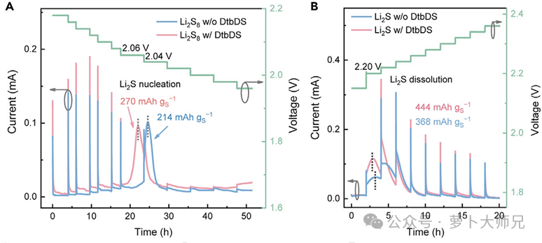
In the PITT test of lithium-sulfur batteries, the discharge and charging processes correspond to the liquid-solid and solid-liquid conversions of polysulfides, respectively. This test allows us to analyze the rate of polysulfide conversion kinetics (through comparison). References: Adv. Mater. 2021, 33, 2007298; Chem. 2020, 6,12, 3297-3311; Angew. Chem. Int. Ed. 2022, 61, e202114671.
As shown in Figure 1, this test was conducted by assembling a lithium-sheet/carbon-paper half-cell. PP was used as the separator. 40 μL of 0.5 mol/L lithium disulfide octahydrate and LiTFSI electrolyte with and without DtbDS (the material studied in the paper) were added to the carbon paper (the exact amount seems to be controlled by adjusting the weight of sulfur). 5 μL of LiTFSI electrolyte was added to the lithium-sheet side. (If this test were for separator modification and cathode catalyst, the materials would be coated onto the carbon paper in the same manner as the deposition and dissolution of lithium disulfide, and then the battery would be assembled and tested).
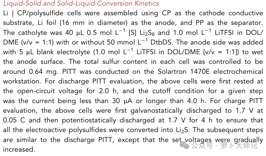
The discharge test process is as follows: Rest two hours, then discharged at a constant voltage under different voltages. The discharge ends when the current is less than 30 microamps or the discharge time reaches 4 hours.
The charging test process is as follows: First, the assembled battery is discharged at a constant current of 0.05C to 1.7V, then discharged at a constant potential of 1.7V for 4 hours to ensure that all active polysulfides are converted to lithium disulfide. Afterwards, the process is similar to the discharge process, except that the voltage is increased gradually.
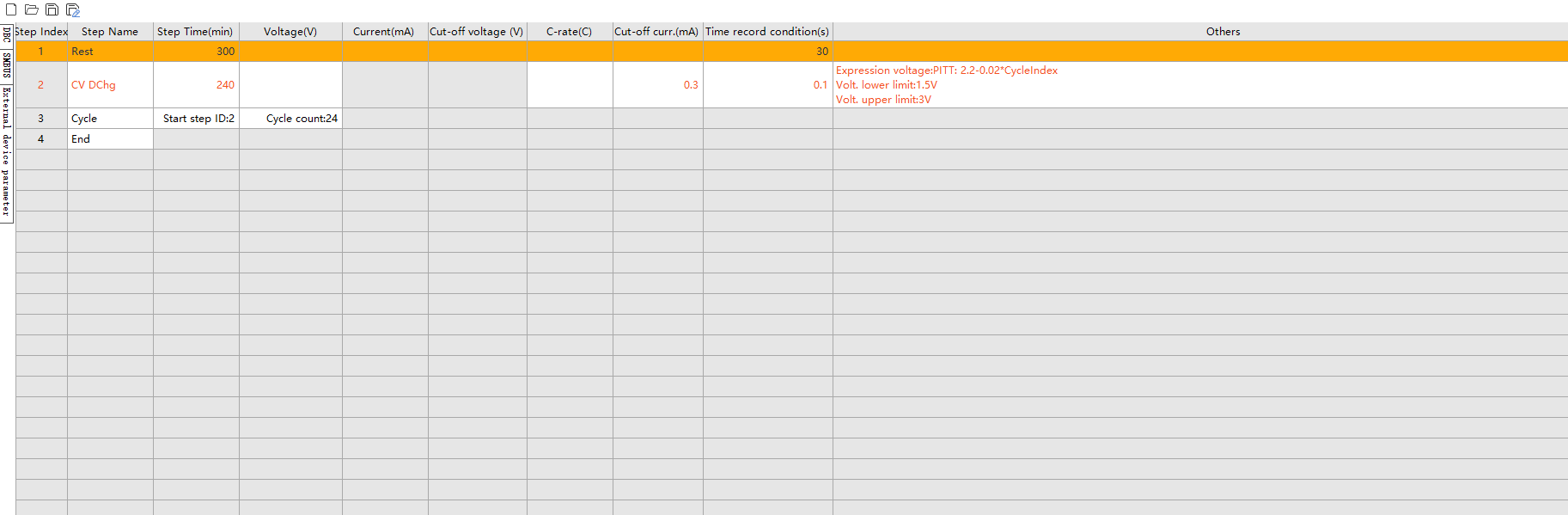
The discharge test parameters are shown in Figure 3 (Neware battery cyclers). The constant voltage discharge time is set to 4 hours, the cutoff current to 30 microamps, and the voltage upper and lower limit protections are set normally. For the voltage expression setting, click on “Other” in step 2 to enter the page shown in Figure 4.
As shown in Figure 4, we click “Others” “Step parameters”, select the “Expression voltage” from the drop-down menu, and then click on the expression section to enter the page shown in Figure 5.
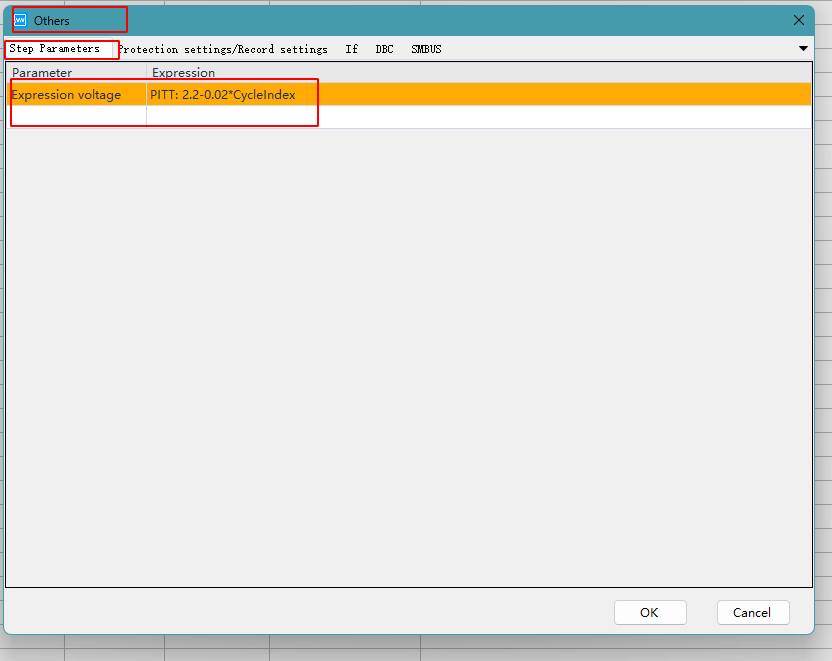
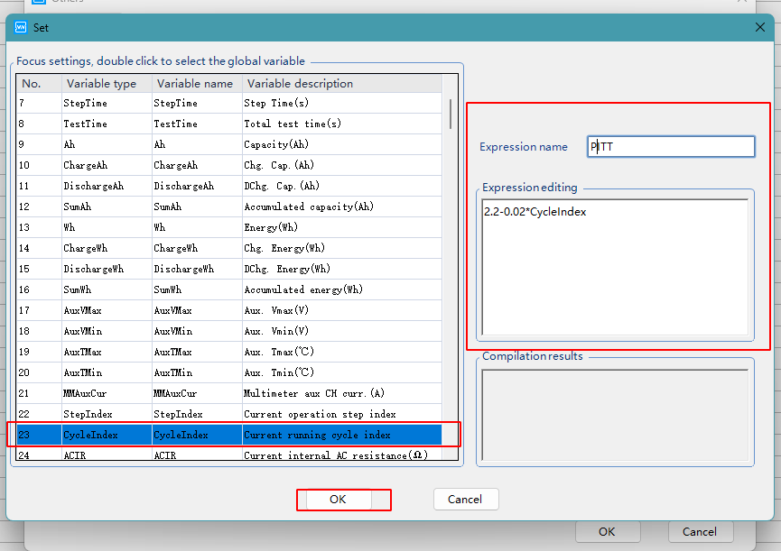
Set the expression name to PITT. In the expression editing box, enter 2.2-0.02*, then scroll down on the left and select CycleIndex. Double-click it to complete the formula input in Figure 4. Click OK to complete the setting. Note that this 2.2V is set according to the voltage of my assembled battery. Starting from that voltage, the voltage is reduced by 0.02V with each cycle. Because the voltage of each assembled battery is different, the voltage here and the number of cycles in step 3 need to be reset. Of course, if you want to avoid the hassle, you can add a constant current discharge process before the constant voltage discharge step, setting the cutoff voltage to 2.2V (the discharge mainly observes the current change around the 2.04V voltage, so we don’t need to run so many voltages before that, and we have to reset them every time. I didn’t think of this when I set it up before, otherwise I would have set the steps this way).
The charging test parameters: Constant current discharge (0.1 C) to 1.7 V, then constant voltage discharge at 1.7 V for 4 hours; then constant current charging (0.1 C) to 2.1 V (because the observed voltage is around 2.16 V, constant current charging to 2.1 V is performed first), followed by constant voltage charging with a cutoff current of 0.03 μA and a charging time of 4 hours. Voltage upper and lower limit protection is set.
For the voltage expression setting, click on “Other”Options in step 5 set “Step parameters”, select the “Expression voltage” from the drop-down menu, and then click on the expression section to enter the page, enter 2.1 + 0.02 * (A – 4) in the expression edit box, A is CycleIndex as Figure 5.
Update: In our formula, we should select the current running step number (StepIndex), not CycleIndex, please have a try.
Due to the limited knowledge and English level is inevitable errors and omissions, if there are errors or infringement of the text, please contact me as soon as possible by private letter, I will immediately be corrected or deleted.