
Take 5 minutes to learn about the BMS (Battery Management System)
Source: WeChat Official Account “Lithium Battery Party” 微信公众号 锂电派
With the widespread adoption of New Energy Vehicles (NEVs), the Battery Management System (BMS), often referred to as the “brain” of the power battery, has become increasingly indispensable. Amidst the fierce competition in the automotive market, any high-performance electric vehicle (EV) must be equipped with an exceptional BMS. In the following sections, we will delve into the functions, architecture, and the vital role that the BMS plays within electric vehicles.
01 Definition of BMS
BMS (Battery Management System) acts as the battery’s “nanny” or “housekeeper.” Its primary duty is to intelligently oversee and maintain individual battery cells. By implementing sophisticated monitoring and safeguards, it safeguards against overcharge and over-discharge, thereby guaranteeing the battery operates safely and lasts longer. Simultaneously, the BMS provides real-time tracking and feedback, offering a full suite of protection and monitoring for the battery’s health.
The hardware architecture of the Battery Management System (BMS) is crucial for ensuring the safe and efficient operation of the battery. Its core functions include real-time monitoring of battery status, such as voltage, current, and temperature estimation, as well as accurate estimation of remaining battery capacity (SOC). Furthermore, the BMS features multiple protection functions, such as preventing overcharging, over-discharging, and overheating, to ensure battery safety. It also actively balances individual cells within the battery pack to maintain battery consistency, thereby extending battery life.
02 BMS Architecture and Components
The architecture of a BMS is the foundation of its functionality. It consists of multiple modules and components working in synergy to complete various battery management tasks. These components include temperature sensors, current sensors, and control units, which are strategically laid out and interconnected to form the complete BMS framework.
Centralized Architecture
Centralized BMS is known for its low cost, compact structure, and high reliability. It is particularly suitable for battery systems with lower capacity and total voltage, such as power tools, robotics, and IoT smart home devices.
High-Voltage Section: Primarily responsible for individual cell voltage acquisition, system total voltage monitoring, and insulation resistance monitoring.
Low-Voltage Section: Encompasses critical components such as power supply circuits, CPU circuits, CAN communication circuits, and control circuits.
Distributed Architecture
Distributed BMS is specifically designed for battery systems with high capacity and high total voltage, such as electric vehicles (EVs) and energy storage systems (ESS). Its modular design allows it to manage large-scale battery systems with ease.
In a distributed architecture, the functions are divided among specialized units:
Cell Supervising Circuit (CSC) / Slave Controller: Responsible for voltage and temperature detection, as well as cell balancing management.
High-Voltage Unit (HVU): Focuses on monitoring the total battery voltage, busbar voltage, and insulation resistance.
Battery Management Unit (BMU) / Master Controller: Responsible for assessing the battery status (SOX estimation), high-level management, and external communication.
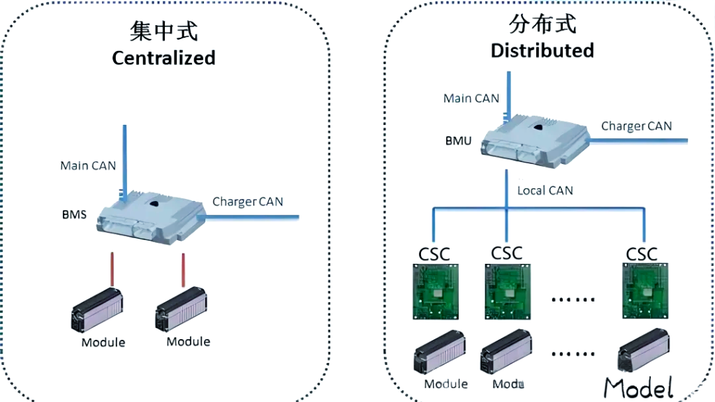
Centralized BMS consolidates all battery management functions into a single central controller, making it ideal for systems with smaller capacities and lower voltages. Its primary advantages include simplified design and reduced communication overhead. However, as battery systems scale up, a centralized BMS may face challenges regarding processing speed and system stability.
In contrast, Distributed BMS is specifically engineered for large-scale, high-capacity, and high-voltage battery systems, such as those found in electric vehicles (EVs) and Energy Storage Systems (ESS). Its modular nature allows individual modules to independently execute specific tasks, such as voltage and temperature sensing as well as cell balancing. This architecture significantly enhances system reliability and flexibility.
03 Core Functions of BMS
Cell Monitoring Technology
Voltage Acquisition: Performs high-precision, real-time monitoring of individual cell voltages.
Temperature Acquisition: Provides continuous tracking of the temperatures of both individual cells and the coolant/thermal management fluid.
Current Detection: Monitors the charging and discharging currents of the battery pack in real-time to ensure an accurate grasp of the battery’s operational status.
SOC (State of Charge) Technology
As a core parameter within the BMS, SOC is directly correlated with the vehicle’s driving range. Through high-precision SOC estimation, the performance of the battery pack can be fully utilized, and the overall usage efficiency can be optimized.
Cell Balancing Technology
Cell balancing aims to ensure energy parity among individual cells within the pack, thereby extending the battery’s service life and optimizing performance.
Passive Balancing: Dissipates excess energy through resistive heating. Its circuit design is characterized by simplicity and high reliability.
Active Balancing: Offers higher efficiency by intelligently transferring excess energy from higher-capacity cells to those with lower capacity, further enhancing the overall efficiency of the battery pack.
Test your battery modules and battery packs
04 Working Principle of BMS
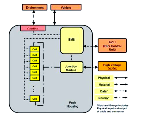
The BMS is intricately integrated with the EV power battery, with the core mission of managing and controlling the battery pack scientifically and efficiently. How does it achieve this functionality?
Specifically, the BMS workflow is as follows:
Real-time Monitoring: Utilizing various sensors, the BMS continuously monitors critical parameters, including the battery’s voltage, current, and temperature.
Status Management: Building upon real-time monitoring, the BMS further manages the battery’s operational status. This includes functions such as leakage detection (insulation monitoring), thermal management, cell balancing, and alarm notifications. Simultaneously, it calculates and reports the battery’s State of Charge (SOC) and State of Health (SOH).
State Estimation and Control: Based on real-time data, the BMS employs advanced algorithms to estimate the battery state and control the maximum output power to ensure optimal driving range. Furthermore, it intelligently controls the charger to achieve optimized current charging.
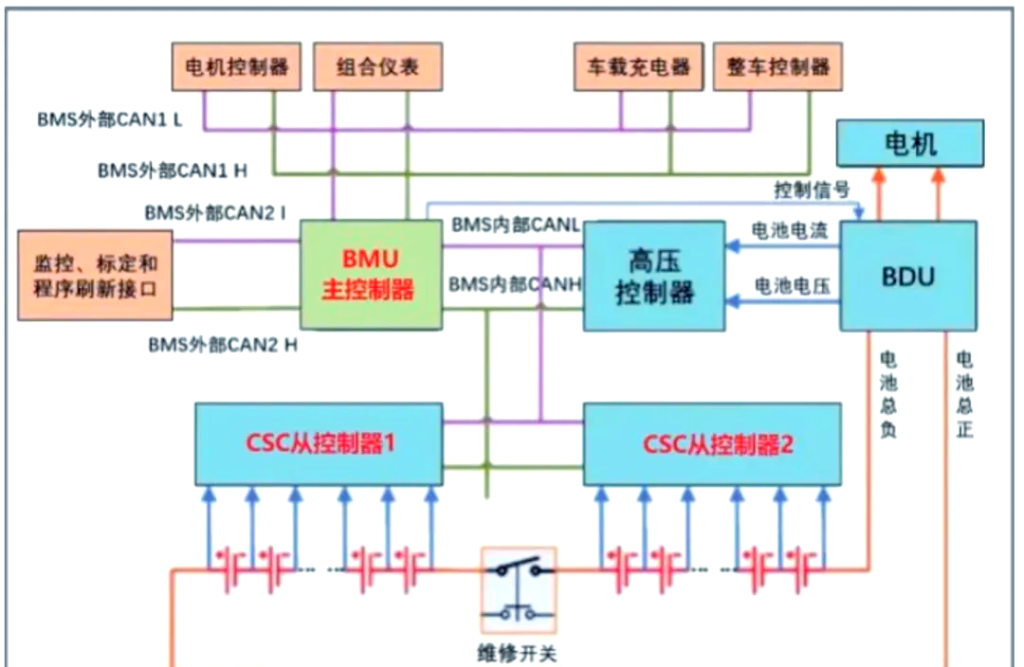
All of this information is exchanged in real-time via the CAN bus interface with the Vehicle Control Unit (VCU), Motor Control Unit (MCU), Energy Control System, and on-board display system. This enables comprehensive monitoring and management of the battery pack. The detailed system architecture is illustrated in the diagram below.
As illustrated in the BMS Architecture Block Diagram, the BMS facilitates real-time data exchange via CAN bus interfaces with various modules, including the Vehicle Control Unit (VCU), Motor Control Unit (MCU), Energy Control System, and the on-board display system. This integration enables comprehensive monitoring and management of the battery pack. Such an architectural design ensures accurate perception of the battery status and timely response, providing a robust guarantee for the safe and efficient operation of electric vehicles.
05 Key Elements for Reliable BMS Operation
To ensure the stable operation of a BMS within a vehicle, several core technical requirements must be addressed.
1) Galvanic Isolation of Power Supplies To prevent mutual interference between BMS modules, isolated DC-DC converters must be employed at the power input stage. In an electric vehicle, multiple BMS modules typically operate simultaneously, all drawing power from the auxiliary battery. Utilizing isolated DC-DC power supplies is crucial to ensure the power independence of each module and to prevent crosstalk. Furthermore, these power supplies should feature a wide input voltage range to accommodate fluctuating operational demands.
2) CAN Communication Isolation To guarantee real-time communication between the BMS and the vehicle, CAN isolation is required at the communication interface. The automotive environment is electromagnetically complex, with interference signals such as surges and transients (pulses). To maintain reliable communication, it is essential to follow the principle of low system coupling and implement safety-regulated power management. Consequently, the CAN interface must be isolated, with high requirements for both protection ratings (IP levels) and transmission rates.
3) High-Voltage Safety Protection The safety of the driver and passengers is paramount, necessitating high-strength power isolation barriers. When multiple cells are connected in series, the pack voltage can reach approximately 500 VDC, posing a significant lethal risk. To safeguard the low-voltage side of the battery system, isolated DC-DC technology is commonly used to provide a clear physical and electrical separation between the high-voltage and low-voltage domains.
Due to the limited knowledge and English level is inevitable errors and omissions, if there are errors or infringement of the text, please contact me as soon as possible by private letter, I will immediately be corrected or deleted.