
Foreword:
Precise, reliable, and efficient testing forms the foundation for obtaining authentic performance data during the research, development, quality verification, and application of lithium-ion batteries. Whether evaluating the intrinsic properties of battery materials or verifying the durability and safety of battery packs under complex operating conditions, standardized and systematic testing is indispensable.
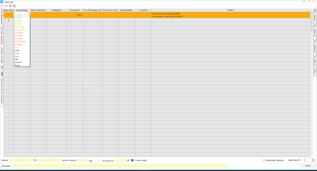
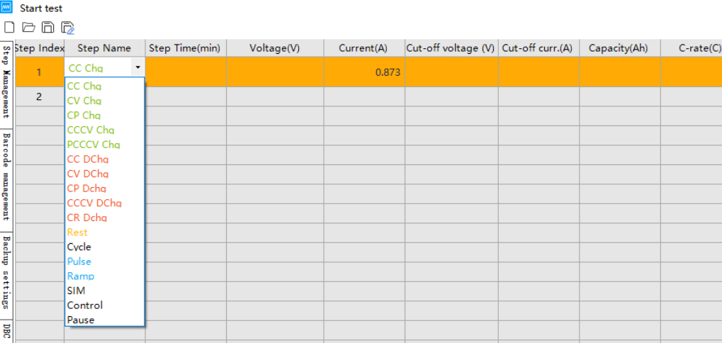
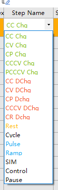
Process steps represent the most critical operations in battery testing, fundamentally involving the precise control of parameters such as current, voltage, power, or resistance. This document systematically introduces common charge/discharge and auxiliary process steps within battery test systems. Using BTS 8.0 software as an example, it details the working principles, key parameter settings, data logging strategies, and typical application scenarios for each charge/discharge process step, as well as auxiliary and control-type process steps.
Charging Process Steps
1. Constant Current Charge
BTS 8.0 Software Abbreviation: CC Chg
Process Description: Charges the battery at a preset constant current until voltage, time, or other termination criteria are met.
Key Parameter Settings:
– Current: Set to a positive value, e.g., 1A, 0.5C (current value automatically calculated in rate mode).
– Termination Conditions: Charge termination voltage (typically 3.6V to 4.5V, depending on battery cathode material) to prevent overcharging. Capacity cutoff or time cutoff may also be set as auxiliary or safety conditions.
Data Logging: Typically recorded at time intervals (e.g., 1-10 seconds) or voltage change intervals (e.g., ΔV=0.001-0.005V). For high-current fast charging, smaller time intervals are recommended to capture voltage variation details.
Application Scenarios: Capacity testing, rate performance testing, charging phase of cycle testing (often paired with CV as CCCV)
2. Constant Voltage Charge (CV Charge)
BTS 8.0 Software Abbreviation: CV Chg
Process Description: Used at the end of charging. Maintains the battery voltage at a constant value, causing the charging current to decay exponentially as battery saturation increases.
Key Parameter Settings:
– Voltage: Set to the charge termination voltage, e.g., 4.2V.
– Cut-off Conditions: Current Cut-off is typically set to a very small value (e.g., 0.05C), indicating that when current decays to this level, the battery is considered fully charged. Time Cut-off is set as a safeguard in case current cut-off cannot be achieved.
Data Logging: Initially, log at time intervals (e.g., 10-30 seconds). As current changes slow later, increase the interval. Strongly recommended to use current change intervals (e.g., ΔI=0.01C) or capacity change intervals (e.g., ΔCap=0.1mAh) to accurately record the current decay curve for saturation level calculation.
Application Scenarios: Battery discharge performance testing, or combined with Constant Current (CC) charging to form CC-CV charging mode.
3. Constant Power Charge (CP Chg)
BTS 8.0 Software Abbreviation: CP Chg
Process Description: Charges the battery at a preset constant power. The system maintains constant power by continuously calculating voltage and current in real-time.
Key Parameter Settings:
– Power: Set the charging power value, e.g., 3W.
– Termination Conditions: Typically set voltage cutoff and time cutoff.
Data Recording: Since power remains constant, voltage and current vary simultaneously. Record real-time curves for power, voltage, and current.
Application Scenarios: Simulating specific charger characteristics; fast-charging research.
4. Constant Current and Constant Voltage Charge (CCCV Charge)
BTS 8.0 Software Abbreviation: CCCV Chg
Process Description: A combined mode of CC Charge and CV Charge, completing two stages in one process.
Key Parameter Settings:
– Current: Current for the constant current stage (e.g., 1C).
– Voltage: Voltage for the constant voltage stage (e.g., 4.2V), also serving as the cutoff voltage for the constant current stage.
– Cutoff Conditions: Current cutoff (for the CV stage) and time cutoff.
Application Scenario: Standard charging profile for lithium-ion batteries.
5. Pack Constant Current Constant Voltage (PCCCV)
BTS 8.0 Software Abbreviation: PCCCV Chg
Process Description: A CCCV charging mode specifically designed for battery packs (Packs) composed of multiple series-connected cells.
Key Parameter Settings:
– Current: Charging current.
– Voltage: Calculated by multiplying the single-cell cut-off voltage by the number of series cells.
– Termination Conditions: Current cutoff and time cutoff.
Data Logging: Same as single-cell CCCV.
– Application Scenario: Direct testing of finished battery packs.
Discharge Process Steps
6. Constant Current Discharge (CC DChg)
BTS 8.0 Software Abbreviation: CC DChg
Process Description: Discharges the battery at a preset constant current until predetermined termination conditions are met.
Key Parameter Settings:
– Current: Discharge current.
– Termination Criteria: Voltage cutoff, capacity cutoff, time cutoff
Data Logging: During capacity testing, record discharge capacity at specified time intervals. For high-resolution discharge curve plotting, log real-time voltage at voltage change intervals (e.g., ΔV=0.001V).
Application Scenarios: Battery discharge performance testing to measure capacity, energy efficiency, cycle life, etc.
7. Constant Voltage Discharge (CV DChg)
BTS 8.0 Software Abbreviation: CV DChg
Process Description: Maintains battery voltage at a constant value during discharge, with current determined by the load.
– Voltage: Set a lower voltage value, e.g., 3.0V.
– Termination Conditions: Typically set to current cutoff or time cutoff.
Data Logging: Logging Interval: Record at time intervals or current change intervals to observe current decay behavior.
Applicable Scenario: Simulates regulated power supply output to test battery load response under constant voltage.
8. Constant Power Discharge
BTS 8.0 Software Abbreviation: CP DChg
Process Description: Discharges at a preset constant power level.
Key Parameter Settings:
– Power: Charging power value
– Termination Conditions: Voltage cutoff and time cutoff.
Data Recording: Records at time intervals. Requires dense recording to analyze the dynamic relationship between voltage and current under constant power conditions.
Application Scenario: Simulates the operational state of actual electrical equipment to test the battery’s peak power output performance.
9. Constant Current and Constant Voltage Discharge (CCCV DChg)
BTS 8.0 Software Abbreviation: CCCV DChg
Process Description: Initiates constant current discharge, transitioning to constant voltage discharge upon reaching the cutoff voltage.
Key Parameter Settings: Similar to CCCV charging, but with negative current and discharge cutoff voltage.
Data Logging:
Logging Interval: Refer to the hybrid strategy for CCCV charging—log by voltage interval during CC phase and by current interval during CV phase.
Application Scenario: Tests requiring complete discharge of battery capacity.
10. Constant Resistance Discharge (CR DChg)
BTS 8.0 Software Abbreviation: CR DChg
Process Description: Simulates discharge with a constant resistive load connected across the battery terminals.
Key Parameter Settings:
– Resistance: Sets the load resistance value
– Termination Conditions: Voltage cutoff and time cutoff.
Data Recording:
Record at time intervals (e.g., 5 seconds) to plot the natural decay curves of voltage and current over time.
Application Scenario: Simulates a simple resistive load.
Auxiliary & Control Steps
11. Rest
Step Description: No current is applied to the battery, placing it in an open-circuit state. This allows the ion concentration gradient and polarization voltage within the battery to relax and stabilize.
Key Parameter Settings:
-Time: Set the rest duration, such as 300 seconds or 1 hour.
-Application Scenario: A necessary step between charge and discharge steps. Used to record open-circuit voltage (OCV), measure battery self-discharge, and allow the battery reaction to stabilize before proceeding to the next step.
12. Cycle
Step Description: Define a series of steps (e.g., CCCV charge -> Rest -> CC discharge -> Rest) as a cycle and set the number of repetitions.
Key Parameter Settings:
-Cycle Count: Set the number of repetitions, such as 1000.
13. Pulse
Step Description: Apply a high-intensity, high-current charge or discharge for a very short period of time, followed by a rest or recovery period. This can be used to test a battery’s instantaneous power capability and internal resistance.
Key Parameter Settings: Current, Pulse Time, Rest Time, Application Scenarios
Application Scenarios: Hybrid Pulse Power Characterization (HPPC) testing, used to calculate internal resistance and power window; and to simulate pulsed operating conditions such as start-stop and acceleration.
14. Ramp
Step Description: Change the voltage or current at a constant slope, rather than a step change.
Key Parameter Settings: Start/Peak/End Voltage, Scan Rate (e.g., mV/s).
Application Scenarios: Used to study battery reaction mechanisms, redox potentials, reversibility, and other aspects of battery performance. This is fundamental research at the materials level.
15. Cyclic Voltammetry
Step Description: An important electrochemical analysis technique. The voltage of the working electrode (cell) is swept at a constant rate, and the resulting current is measured.
Key Parameter Settings:
Start/Peak/End Voltage, Scan Rate (e.g., mV/s), Cycle Count.
Application Scenario: Used to study battery reaction mechanisms, redox potentials, reversibility, and other fundamental research at the materials level.
16. Simulation (SIM)
Step Description: Import a data file consisting of time-current or time-power data, allowing the test system to accurately reproduce this complex charge-discharge waveform.
Application Scenario: Simulating real-world application scenarios, such as EV UDDS and WLTC operating conditions, and daily mobile phone usage, is the most direct way to verify battery performance in real-world applications.
17. Control Step (Control)
Step Description: Commands used to control other channels or devices. They do not charge or discharge the battery in the current channel.
Key Parameter Settings:
Control commands (e.g., turning other channels on/off, triggering external devices).
Application Scenario: Multi-channel coordinated testing. For example, when a step in one channel reaches a certain condition, another channel is triggered to start testing.
18. Follow Step
Step Description: Causes the test parameter (e.g., current) of one channel to follow the value of another channel in real time.
Key Parameter Settings:
Followed channel number, scaling factor.
Application Scenario: Used for battery pack testing, where the master channel controls the overall pack, and the slave channel follows the master channel’s current, simulating the behavior of a single cell in the pack; or for comparative testing.
19. Pause
Step Description: Program execution automatically pauses at this point, waiting for user confirmation before continuing. A prompt message will typically appear.
Key Parameter Settings: Pause trigger condition (e.g., pause after every 5 cycles).
Application Scenario: Used when manual intervention is required during testing, such as changing the test environment (resuming testing after placing the battery in an incubator) or connecting additional measurement equipment.

If you do battery research or battery materials research, you might be interested in these:
More tips for using NEWARE software are here: