
A Guide to Making Highly Reproducible Li-Ion Single-Layer Pouch Cells for Academic Researchers
Publication Details
Title: A Guide to Making Highly Reproducible Li-Ion Single-Layer Pouch Cells for Academic Researchers
Journal: Journal of The Electrochemical Society (Impact Factor: 3.9)
DOI: 10.1149/1945-7111/aceffc
Research Team: Department of Physics and Atmospheric Science, Dalhousie University, Canada; NOVONIX Battery Technology Solutions.
Research Summary: To address the performance gap between the coin cells commonly used in academia and industrial-grade multilayer pouch cells, this study proposes a fabrication method for single-layer pouch cells (SLPs) featuring a no-overhang design. By optimizing electrode alignment and packaging processes, this approach significantly enhances the reliability and industrial relevance of battery testing.
I. Research Background and Significance
With the rapid advancement of lithium-ion batteries in the consumer electronics and electric vehicle sectors, the choice of cell format in academic research is often overlooked. Traditional coin cells—which typically utilize lithium metal or oversized graphite anodes—yield test results that differ significantly from those of commercial pouch cells.
This study aims to compare the performance of various cell formats and provide a comprehensive guide for fabricating highly reproducible single-layer pouch cells (SLPs). By doing so, it seeks to assist the academic community in obtaining results that are more closely aligned with industrial standards and practical applications.
As lithium-ion batteries have seen an explosive surge in popularity driven by the consumer electronics and electric vehicle industries, the research community has expanded rapidly. Many of these researchers may be unaware of the pitfalls involved in selecting an appropriate cell format to obtain industrially relevant results. While the simplest format requiring the least active material is the coin cell, it is far from representative of commercial lithium-ion batteries. Typically, coin cells utilize an excess of lithium metal as a counter electrode (half-cells)¹, low active material loading, excessive electrolyte volume, and a large negative-to-positive (N/P) capacity ratio, all of which can distort the perceived performance of a given electrochemical system. Furthermore, the assembly processes and component quality used in coin cell fabrication can significantly impact the representativeness and reproducibility of electrochemical results¹⁻³.
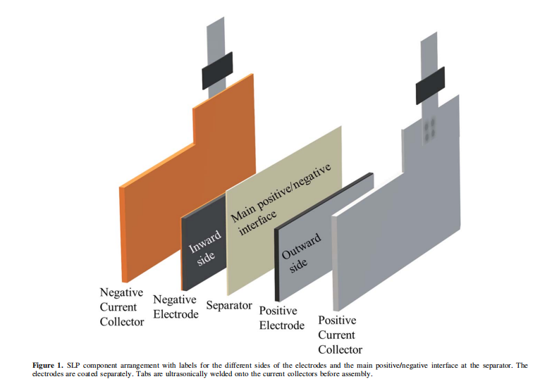
Consequently, academic researchers are increasingly adopting highly reproducible, industrial-quality wound pouch cells for more precise studies⁴⁻⁷. However, these wound cells are not always practical—particularly for evaluating novel active materials—as they require significantly more material than is typically synthesized at a laboratory scale. An alternative format that bridges the gap between coin cells and machine-made pouch cells is the single-layer pouch cell (SLP), the primary components of which are illustrated in Figure 1. SLPs generally require less active material than machine-made pouch cells, yet their format allows for the control of stack pressure and electrolyte volume while remaining compatible with gas evolution analysis (Archimedes measurements). Therefore, one objective of this study is to compare the cycling performance of coin cells, multilayer stacked pouch cells, and SLPs, while providing clear, definitive instructions for the assembly of the latter.
Another unfortunate aspect of many full-cell designs is the requirement for an anode “overhang.” This overhang means that the anode is larger than the cathode in every dimensional area. If any portion of the cathode extends beyond the boundary of the anode, Li+ ions deintercalating from the cathode will plate onto the edges of the anode. Lithium plating is undesirable as it irreversibly consumes the lithium inventory and can lead to hazardous dendrite formation. Consequently, battery manufacturers—both in laboratory and industrial settings—typically employ a 1 mm overhang in every direction (as seen in the stacked pouch cells used in this study) to minimize the risk of the cathode extending beyond the anode boundary during electrode stacking or winding. However, this results in lithium being effectively trapped in the overhang region of the anode at higher C-rates due to the longer Li+ diffusion paths⁸. While this is a necessary trade-off in modern commercial lithium-ion battery manufacturing, the overhang area usually represents only a small fraction of the total anode area in commercial cells. In contrast, it can constitute a significant proportion in laboratory coin cells, potentially leading to discrepancies in cycling tests.
During the assembly of industrial stacked or wound cells, there is always a region where a double-sided coating on one side (typically the anode) is unnecessary; therefore, single-sided electrodes should be used. However, not all manufacturers eliminate the outward-facing second side, opting instead to simply use double-sided coatings throughout. Similarly, researchers fabricating lab-scale cells using electrode discs punched from double-sided coatings of machine-made cells may attempt to assemble them as-is into coin cells or SLPs. The unnecessary use of double-sided coatings is also shown to be detrimental, as the extra outward-facing negative side traps lithium—effectively increasing the overhang area and the N/P ratio—while an outward-facing positive side means more lithium is available during cycling than predicted³. Therefore, SLPs with overhang, without overhang, and with double-sided coatings will be compared using precise Ultra-High Precision Coulometry (UHPC) cycling tests. It will be demonstrated that no-overhang SLPs not only outperform all other SLP types but also surpass all other tested cell formats, providing the most authentic cycling results for the electrode materials under investigation.
II. Experimental Section
Electrode Coating
Electrode coatings were obtained from the pilot-scale coating facilities at NOVONIX Battery Technology Solutions (Bedford, NS, Canada). The double-sided cathode coatings were calendered at NOVONIX and consisted of 94.0% single-crystal NMC622 (designated as “EA622”; ME6SC, Beijing Easpring Material Technology Co., Ltd., China), 4.0% carbon black (Super P, Imerys, Switzerland), and 2.0% polyvinylidene fluoride (Solef 5130 PVDF, Solvay, Belgium), coated onto a 15μm aluminum foil.
The anode coatings comprised 94.5% artificial graphite (AML400, Guangdong Kaijin New Energy Technology Co., Ltd., China), 1.3% carbon black (Super P, Imerys, Switzerland), 2.8% styrene-butadiene rubber (BM-451B SBR, Zeon, USA), and 1.4% carboxymethyl cellulose (Sunrose MAC-350HC CMC, Nippon Paper Industries Co., Ltd., Japan), coated onto a 10μm copper foil. These anodes included a combination of calendered double-sided and uncalendered single-sided coatings, which were calendered at a pressure of 2000 atm using a calender at Dalhousie University (DPM Solutions Inc., Hebbville, NS, Canada). In most cases, unless otherwise specified, one side of the coating for SLPs and coin cells was stripped using N-methyl-2-pyrrolidone (NMP) (for cathodes) or a combination of ethanol (due to the hydrophobicity of graphite) and distilled water (for anodes). Following stripping, the now single-sided coatings were vacuum-dried at 90°C for several hours to remove any residual solvents. The single-sided loading was 12–13 mg cm⁻² for the anodes and 20–21 mg cm⁻² for the cathodes.
Electrolyte
The electrolyte used in all cells consisted of a mixture of ethylene carbonate (EC), ethyl methyl carbonate (EMC), and dimethyl carbonate (DMC) in a weight ratio of 25:5:70 (w/w) (water content < 20 ppm; Capchem, Shenzhen, China), with 1.5 M LiPF₆ (Capchem) salt. The formulation also included 2% by weight vinylene carbonate (VC) and 1% ethylene sulfate (also known as 1,3,2-dioxathiolane 2,2-dioxide; DTD) as additives. All electrolyte components were used as received and were prepared and stored in an argon-filled glovebox.
Coin Cells
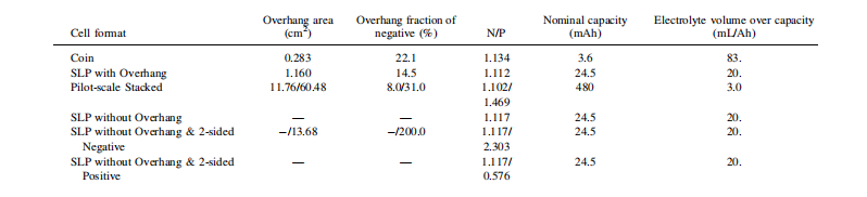
CR2325 (23 mm diameter, 2.5 mm height) full coin cells were assembled using single-sided anodes obtained from NOVONIX and stripped double-sided cathodes. The anodes were punched into 12.75 mm diameter discs, while the cathodes were punched into 11.25 mm diameter discs. All electrodes were punched after calendering, with the uncoated foil side facing “up” toward the press and placed within folded weighing paper to prevent coating delamination. The overhang area, the proportion of the overhang relative to the total anode area (i.e., the portion not facing the cathode), and the N/P ratio are summarized in Table I, alongside the nominal capacity for each cell format. The electrodes were then vacuum-dried at ≥90°C for approximately 10 hours and transferred into an argon-filled glovebox for fabrication.
CR2325 half-cells were assembled, consisting of a cathode, a single layer of blown microfiber polypropylene separator (BMF; thickness 0.275 mm, 3.2 mg cm⁻²; 3M Company, St. Paul, MN, USA), and an anode. The hardware included 400-series stainless steel bases (Kaga Steel, Japan), polypropylene gaskets (Adair Plastics, Minneapolis, MN, USA), 304 stainless steel spacers (Boker’s, Inc., Minneapolis, MN, USA), stainless steel Belleville washers (Schnorr Corporation, Ann Arbor, MI, USA), and 300-series stainless steel caps (Kaga Steel, Japan). Each cell contained a total of 15 drops of electrolyte (approx. 20μl per drop; ~0.3 mL total), corresponding to the highest electrolyte-to-nominal-capacity ratio of 83 mL/Ah, as shown in Table I. The crimped coin cells were then removed from the glovebox, and an epoxy sealant (Loctite 1C Epoxi-Patch Hysol, part number 1373425, Henkel, USA) was applied to the crimp seal to prevent electrolyte evaporation during long-term cycling at elevated temperatures. These coin cells had a theoretical capacity of 3.6 mAh, as listed in Table I.
Testing and Cycling. The coin cells were cycled using a Maccor Series 4000 tester (Tulsa, OK, USA) in a temperature-controlled chamber maintained at 40.0±0.1°C. Prior to formation, the cells were charged to 1.5 V (vs. graphite) at a rate of ≤C/20 and held at this voltage for a 12-hour wetting period. Formation consisted of one constant-current (CC) cycle between 3.0 and 4.2 V (vs. graphite) at a C/20 rate. Subsequently, long-term cycling was performed within the same voltage limits using a C/3 CC charge and a C/3 CCCV (constant-current constant-voltage) discharge. The CCCV discharge was adopted due to the relatively large anode overhang area of this design compared to others (see Table I). Every 49 cycles at C/3 was followed by a CC cycle at C/20, referred to as a “check cycle,” which was repeated until a total of 251 cycles was reached.
Single-Layer Pouch Cells (SLPs)
SLPs were assembled using single-sided electrodes obtained from NOVONIX. Cathodes were punched using a 1.8 x 3.8 cm² rectangular die (Apple Die, USA), while anodes were punched using either the same die (for “no-overhang” cells) or a 2.0 x 4.0 cm² die, as illustrated in Figure S1. The electrode punching followed the same procedure as the coin cells to prevent coating delamination. Given that the electrode loading was identical across all cell designs, only 100–130 mg of active material was required per electrode with these dimensions. All overhang areas (where applicable) and N/P ratios are summarized in Table I.
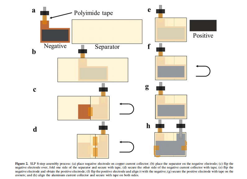
Similar to the way the anode contacts the steel spacer in a coin cell, for SLPs, the punched electrodes were placed onto aluminum (cathode) or copper (anode) current collectors to establish an electrical connection with the external circuit, as shown in Figure 1. These independent current collectors were fabricated from 50μm aluminum or copper foil (McMaster-Carr, USA) and punched using the dies shown in Figures S1a and S1d. Tabs provided by NOVONIX were ultrasonically welded to the 1.0 cm protruding “top” section of the current collectors. The tab materials were 100μm thick nickel for the copper current collectors and aluminum for the aluminum current collectors (Almighty Power Electronic Co., Limited, Hong Kong). For the anode current collector, most of the nickel metal beneath the sealing polymer was covered with polyimide tape (Kapton Tape, 3M/DuPont, USA), as shown in Figure 2a, to prevent nickel dissolution. The finished current collectors were cleaned with ethanol or isopropanol prior to further assembly.
More details: A Guide to Making Highly Reproducible Li-Ion Single-Layer Pouch Cells for Academic Researchers