
The ever-increasing demand for large-size lithium-ion batteries from electric vehicles has driven the accelerated development of cell specifications with higher energy density and better pack efficiency. By the end of 2024, electric vehicles accounted for approximately 4% of the global passenger vehicle fleet, and this is projected to quadruple by 2030. For automotive applications, LIB (Lithium-ion Battery) R&D revolves around cost, energy density, and power capability, while also considering safety and lifespan, resulting in various chemical systems, cell specifications, and integration solutions. EV batteries range from 18650 cylindrical cells (≈3 Ah) to large-size pouch and prismatic cells exceeding 100 Ah, each with trade-offs in cycle life, thermal performance, energy density, and safety.
Tesla launched its 4680 cylindrical cell for the Model Y platform in 2020, with a volume and capacity approximately five times that of the previous generation 21700. Combined with a tabless design, it aims to achieve higher energy density without sacrificing manufacturing efficiency and production costs. Another leading battery manufacturer, BYD, has also developed innovative cells for its electric vehicle platform—the “blade battery” prismatic solution using lithium iron phosphate (LFP) chemistry, emphasizing safety, lifespan, and cost. However, BYD is also using and mass-producing 4680-size LFP/graphite cylindrical cells in its electric vehicles and energy storage systems (ESS), and other battery manufacturers are following suit with larger-size cells.
[Work Introduction]
In this study, Professor Ying Shirley Meng from the University of California, San Diego, and Peter M. Attia and so on from Glimpse, a battery scanning company in Massachusetts, conducted a comprehensive analysis of BYD‘s 4680 LFP/graphite cylindrical lithium-ion battery cell. Through systematic physical disassembly, X-ray imaging, electrochemical testing, and electron microscopy, the performance and structure were evaluated from the cell level down to the material level. Disassembly and X-ray results revealed that the cell employs a rare multi-tab design with uniform coating on both sides of the electrodes, and no silicon material is added to the graphite anode. Electrochemical testing showed that its energy density reaches 374.6Wh/L and 150.5Wh/kg. Furthermore, hybrid pulse power characteristics (HPPC) and electrochemical impedance spectroscopy (EIS) further demonstrated that the cell possesses excellent rate performance: at different states of charge (SOC), the cell’s DC areal impedance is only 6~17 Ω·cm², and the charge transfer areal impedance is approximately 5.9 Ω·cm². Therefore, these findings provide empirical evidence for new directions in the design and performance of the 4680 specification, laying a solid foundation for the future development of large-size cylindrical battery technology. The BYD 4680 studied in this paper is the second 4680 specification cell to be publicly characterized, following the Tesla 4680.
The relevant research results, titled “Design and Performance of the BYD LFP/Graphite 4680 Cylindrical Cell,” were published in the Journal of The Electrochemical Society.
[Content Description]
BYD 4680 Cylindrical Battery Cell Structure and Core Design
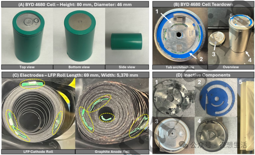
All tested cells in this study were independently purchased from online suppliers. Preliminary inspection before disassembly revealed that the BYD 4680 cylindrical cell was encased in insulating heat-shrink tubing (Figure 1A), while the Tesla 4680 had a nickel-plated steel shell without direct insulation. Energy dispersive spectroscopy (EDS) confirmed that the BYD 4680 shell was nickel-plated steel: rich in Fe in the cross-section and Ni in the surface. A small pressure relief valve was located next to the negative electrode cap on the top of the cell. The measured height of the BYD 4680 was 80 mm and the diameter was 46 mm, consistent with specifications. Similar to the Tesla 4680, the BYD 4680 shell also served as the negative terminal, and the positive electrode cap was insulated from the shell by a white rubber gasket (Figure 1B “3”).
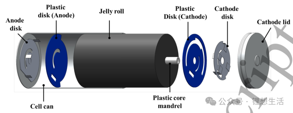
After cutting open the cell, it was found that the positive electrode cap was still connected to the metal positive electrode disc (Figure 1B “1”). After cutting with ceramic shears, the positive electrode disc, the core, the blue plastic disc (“2”), and the hollow plastic shaft in the center of the core (“5”) were visible. A metal negative electrode disc (“4”) was also present at the bottom of the casing, directly spot-welded to the bottom. After removing the bottom casing with a tube cutter, the connection between the negative electrode tab and the negative electrode disc was severed with ceramic shears, completely detaching the core from the top and bottom.
After removing the core, the tape was removed and the core was unrolled, revealing the positive electrode, negative electrode, and separator. Figure 1C shows that the LFP positive electrode coil is 69 mm high and 5370 mm long; the graphite negative electrode coil is 71 mm high and 5513 mm long, 143 mm longer than the positive electrode. There are four aluminum tabs on the positive electrode and three nickel tabs on the negative electrode, arranged along the length of the electrode, covered with a PET insulating film. Although the innermost nickel tab of the negative electrode is completely wrapped in PET, it is not welded to the casing.
The remaining inactive components are shown in Figure 1D: The metal positive electrode disk is 0.31 mm thick, with an asymmetrically enlarged outer edge and circular, semi-circular, and rectangular notches for the aluminum tabs and PET tape to pass through; a 0.29 mm thick blue plastic positive electrode disk is sandwiched between it and the positive electrode cover, serving as insulation to prevent accidental contact with the copper current collector of the winding core. Four aluminum tabs are welded to the metal positive electrode disk at ~90° intervals, with radial extension distances of 0.4, 13.1, 16.0, and 18.3 mm, respectively. The metal negative electrode disk is 0.31 mm thick, with only a semi-circular notch and no central hole, and is directly spot-welded to the bottom of the shell; the three nickel tabs have radial distances of 9.0, 15.6, and 20.0 mm, and a plastic disk of the same thickness is used for insulation between the disk and the winding core to prevent short circuits between the aluminum current collector and the shell.
To provide a direct and quantitative analysis of the BYD 4680 structure, 3D X-ray computed tomography (CT) was used to achieve non-destructive whole-core imaging. Figure 3A’s 2D radial section clearly shows the internal structure, with contrast corresponding to each component. The magnified view (Figure 3B) clearly shows the contrast between the plastic central shaft and the electrodes, with a hexagonal cavity inside the shaft, which was confirmed optically after disassembly. Figure 3C’s axial rotation section provides a full-body view, and Figure 3D further distinguishes the layered electrodes, tabs, and electrolyte meniscus. Excess electrolyte at the meniscus suggests the need to investigate the function of the central shaft.
The measured central shaft height is 7.1 mm, consistent with the height of the negative electrode coil. Conventional cylindrical batteries use the central shaft to suppress radial deformation or provide an venting channel in case of thermal runaway. To verify whether the BYD design surpasses traditional functions, ethanol was first injected into the hexagonal cavity under normal pressure, with no leakage. Then, after vacuum drying in a glove box, it was immersed in LP57 electrolyte for two weeks, showing almost no weight gain, indicating that the shaft does not absorb liquid and mainly serves as structural support, preventing core collapse under fast charging or thermal shock. Simultaneously, infrared spectroscopy identified the central shaft material as polypropylene (PP), not polyethylene (PE), therefore the diaphragm is PP. SEM observation revealed submicron pores on the surface with a uniform cross-section, confirming a single-layer structure. Consistent with CT results, the hexagonal cavity is 2.5 mm long, with a cross-sectional area of approximately 16.24 mm², and a wall thickness of approximately 0.66 mm.
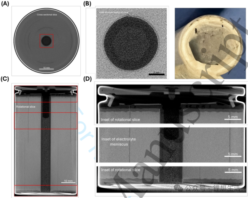
By examining different radial (cross-sectional) CT slices of BYD 4680 cells, the internal structure and features of the cells can be examined more precisely. Starting from the bottom first frame (Z=0) in Figure 4A, the metal negative electrode disk and the three nickel tabs welded to it (highlighted in yellow) are clearly distinguishable; moving upwards along the Z-axis, the four aluminum positive electrode tabs also appear successively. The bright area in the top slice of Figure 4A corresponds to the welding point on the metal positive electrode disk. Due to the different tab materials, the X-ray absorption contrast varies significantly; the axially rotated slice in Figure 4B easily distinguishes the four aluminum positive electrode tabs (C1-C4) from the three nickel negative electrode tabs (A1-A3).
To quickly and automatically analyze the cell CT data, the Glimpse post-processing workflow reported by Condon et al. was used to segment the center of 25 BYD 4680 cores (blue overlay in Figure 4A), quantifying the area and roundness of the central region. Roundness was defined as the ratio of the minimum/maximum diameter of the ellipse fitting. The center area and roundness of the 25 cells showed extremely high consistency, with relative standard deviations of 0.546% and 0.467%, respectively (Figure 4C); the lowest roundness still reached 97.2%, far exceeding that of conventional cylindrical cells. This high uniformity highlights the advantages of the cylindrical design with a central axis: significantly enhancing mechanical stability and reducing the risk of deformation under stress.

Electrochemical Performance Testing
If you also need to test battery performance, please click here. Neware battery tester.
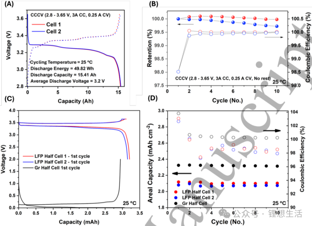
All tests in this section were repeated on two independent cells. Cycling was performed in the 2.8–3.65 V range using a C/5 (3 A) constant current-constant voltage (cutoff C/60) protocol. The measured discharge capacity was 15.41 Ah, energy was 49.82 Wh, and the average plateau was approximately 3.2 V. The graphite step and FePO4↔LiFePO4 plateau were clearly defined, confirming the LFP/graphite system (Figure 5A). Based on this, the calculated weight and volumetric energy densities were 151 Wh kg⁻¹ and 374.6 Wh L⁻¹, respectively, approximately 60% of that of Tesla NMC 4680. This is mainly limited by the low intrinsic energy of LFP and the redundant mass of the current collector and separator due to the longer electrode. After 10 consecutive cycles without rest, the capacity decay was <0.1%, and the CE increased week by week, indicating initial stability (Figure 5B).
To obtain accurate areal capacity, a single-sided coating was mechanically scraped from the removed electrode roll, and 13 mm (positive electrode) and 12.7 mm (negative electrode) discs were cut and assembled into CR2032 half-cells. LP57 electrolyte was used, and the first cycle of C/10 showed the characteristics of LFP single-platform and graphite multi-platform (Figure 5C). Continuing with the C/5 cycle, the average reversible capacity was 2.77 mAh (positive electrode) and 2.96 mAh (negative electrode), corresponding to single-sided areal capacities of 2.09 mAh cm-2 and 2.34 mAh cm-2, with an N/P ratio of 1.1.
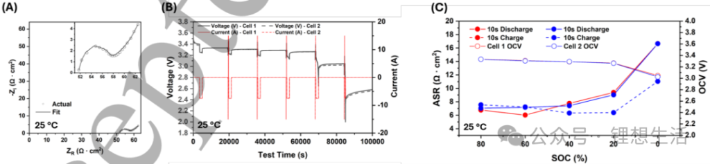
Using the newly purchased BYD 4680, EIS measurements at 20% SOC showed an RCT of only 5.9 Ω·cm² and Rs of 51.5 Ω·cm². HPPC analysis revealed that the DC internal resistance increases with decreasing SOC, with a more significant increase in the discharge direction, particularly noticeable in the low to medium SOC region. This demonstrates the low impedance advantage of the LFP system, which is less sensitive to changes in SOC compared to NMC/NCA systems.
Further rate testing was conducted on the BYD 4680. Based on the rated capacity of 15 Ah, symmetrical charge and discharge cycles were performed at C/2, 1C, and 2C (7.5, 15, and 30 A), each for 5 cycles. After CC, CV was added to C/60. The voltage curves in Figure 7A highly overlap, showing good consistency. As the rate increases, the CV capacity ratio increases, with ~15.00 Ah available at C/2 and dropping to 13.25 Ah at 2C; after dropping back to C/2, it can still recover nearly 15 Ah (Figure 7B). In the 5th cycle, the capacity utilization of 1C and 2C reached 94.7% and 87.9% respectively, and CE stabilized at 99.8% after the first cycle. Compared with the Tesla 4680, the BYD’s 1C and 2C charging amounts were 97.8% and 92.7% of the rated values, respectively, far exceeding the competitor’s 82.8% and 71.0%, further confirming its “power-oriented” positioning. It should be noted that while continuous fast charging at ≥2C generates heat and suppresses lithium deposition, it may be accompanied by side reactions and SEI thickening; while fast discharge, due to its higher potential, has fewer such side reactions.

Highly recommend the Neware environmental chamber: 0~60℃ temp chamber, high and low temperature chamber.
Material Characterization
To further analyze the LFP and graphite electrodes, SEM characterization was performed. Figure 8 shows top-view and cross-sectional photographs of the positive and negative electrodes.
Positive electrode: The cross-sectional measurement shows an electrode thickness of approximately 150 µm and an aluminum current collector thickness of approximately 10 µm (Figure 8A), consistent with the results from micrometer screw gauge and CT slice analysis. Top view (Figure 8B) reveals 100–300 nm nano-sized LFP primary particles; this size shortens the lithium-ion diffusion path and improves the rate of change. The carbon coating on the LFP surface is <10 nm, difficult to distinguish with SEM. EDS also detected approximately 0.3 at% Ti, suggesting that Ti doping can shrink the lattice and further shorten the diffusion channel, synergistically improving performance with nano-sizing.
Negative electrode: The electrode layer thickness is approximately 125 µm and the copper current collector thickness is approximately 10 µm (Figure 8C), consistent with the five-point thickness measurement and CT average. Compared to Tesla 4680 single-layer graphite, the BYD coating is 54.5 µm thick, a 54% reduction, which lowers internal resistance and improves heat dissipation, beneficial for fast charging and high power. Top-view SEM (Figure 8D) showed flake graphite particles with a diameter ≤10 µm; EDS detected only graphite, no silicon, C atomic ratio 91.2%, containing carbon black and binder; Na accounted for 1.8%, suggesting the possible use of CMC binder. Recent dry processes rely on polymer fibrillation to increase loading, but no fiber morphology was observed on either electrode, indicating that traditional wet coating is still being used.

[Summary]
In summary, this article systematically analyzes the design and characteristics of BYD’s 4680 cylindrical lithium iron phosphate battery. Disassembly reveals double-sided electrode coating and a hexagonal hollow plastic central shaft within the core. Both positive and negative electrodes have multi-tab structures, but the innermost tab of the negative electrode lacks an external terminal. The central shaft provides only mechanical support and has no additional ventilation or liquid absorption function. Furthermore, CT analysis of 25 cells shows extremely high consistency in core roundness and area. SEM reveals nanospherical LFP on the positive electrode and sheet-like graphite on the negative electrode. EDS confirms trace amounts of Ti doping in the LFP, the absence of silicon in the negative electrode, and the absence of dry-process fiber morphology in both electrodes, indicating the use of a traditional wet-process technology. The cell-level energy density is 374.6 Wh/L and 150.5 Wh/kg. EIS and HPPC both show milliohm-level internal resistance, with a significant increase in the low SOC region. Furthermore, the 1C/2C rate capacity utilization rates reach 94.8% and 88.1% respectively, and combined with the ultra-thin graphite coating, it highlights its high-power positioning. Therefore, this paper confirms the feasibility of LFP in high-power scenarios in large cylindrical applications, providing new ideas for EVs and energy storage, and points out that thermal management and cathode surface engineering can be further optimized.
[Article Information]
Alex Liu, Weiliang Yao, Shaojie Yang, David Gonsoulin, Aiden Larson, Amariah Condon, Peter M. Attia,* Ying Shirley-Meng*, Design and Performance of the BYD LFP/Graphite 4680 Cylindrical Cell, Journal of The Electrochemical Society, https://doi.org/10.1149/1945-7111/ae1e33
Due to the limited knowledge and English level is inevitable errors and omissions, if there are errors or infringement of the text, please contact me as soon as possible by private letter, I will immediately be corrected or deleted.