
How to assemble and test a three electrode pouch cell?
The Role of Three-Electrode Systems in Battery Analysis
When a battery undergoes low-temperature or high-rate charging, lithium ions reaching the anode may fail to intercalate into the graphite layers in time, leading to lithium plating. This is a polarization phenomenon caused by kinetic limitations. Therefore, to better investigate various electrochemical properties, a reference electrode is often introduced. This allows for the independent measurement of the cathode and anode potentials relative to the reference, as well as their potential variations under different testing conditions.
By utilizing a three-electrode system, researchers can perform comprehensive, in-situ analysis on several fronts: the film-forming reactions during formation, cycle life, rate capability, high/low-temperature performance, quantitative analysis of lithium plating, impedance evolution of both electrodes, and battery failure mechanisms. During the pre-charge and formation process, the reference electrode provides the voltage changes of the cathode and anode against a stable baseline, enabling the in-situ detection of internal electrochemical reactions.
Furthermore, when a battery undergoes high-rate charging or discharging, the median voltage typically decreases as the C-rate increases. The application of a three-electrode system can effectively decouple and analyze the degree of polarization for the cathode and anode individually, allowing for targeted performance improvements. In this study, a lithium metal chip or a lithium-plated copper wire is used as the reference electrode to investigate the electrochemical behavior of each internal electrode during the charge-discharge process via electrochemical testing.
1. Experimental Section
1.1 Selection of Graphite Anode Materials
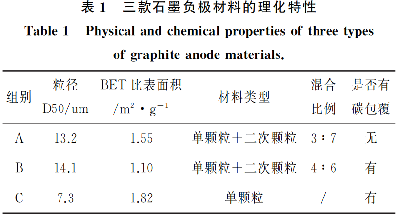
The physical and chemical characteristics of the three graphite anode materials are summarized in Table 1. Since particle size, particle morphology, and carbon coating treatments significantly influence the kinetic performance of graphite, these three distinct types of graphite materials were selected for comparative analysis.
1.2 Material Characterization
The morphologies of the three graphite anode materials were characterized and analyzed using a Scanning Electron Microscope (SEM) (Zeiss EV018, manufactured in Germany).
1.3 Battery Assembly: Make a three electrode pouch cell
1.3.1 Preparation of the Reference Electrode
An enameled copper wire with a diameter of 40um was selected and subjected to the following processing steps.
- Step 1: Immersion in concentrated H2SO4 for 3 h
- Step 2: Rinsing with anhydrous ethanol
- Step 3: Immersion in dilute HCl for 20 min
- Step 4: Ultrasonic cleaning with deionized water
- Step 5: Oven drying (below 50 °C)
1.3.2 Fabrication of three electrode pouch cells
Lithium Iron Phosphate (LFP) was selected as the cathode material, while different types of graphite were matched as anodes for the study. The cathode consists of LFP, polyvinylidene fluoride (PVDF), and conductive carbon black (Super P). The anode is composed of the aforementioned graphite types, Super P, sodium carboxymethyl cellulose (CMC), and styrene-butadiene rubber (SBR). A 20μm PP (polypropylene) base film was used as the separator. The electrolyte contains 1 mol/L LiPF6, with a solvent mixture of EC:EMC:DEC (weight ratio of 25:40:30) and 2% VC (vinylene carbonate).
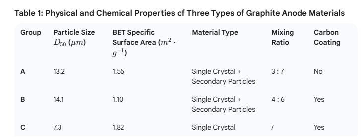
The anode, separator, and cathode were assembled into a pouch cell using Z-fold stacking. The design utilized an N/P ratio of 1.15 and a design capacity of 5 Ah. Based on the Z-fold stacking method, the reference electrode was integrated by following the sequence of Cathode / Separator / Reference Electrode / Separator / Anode. The tab of the reference electrode can be led out from the top, sides, or bottom of the pouch cell (as shown in Figure 2).
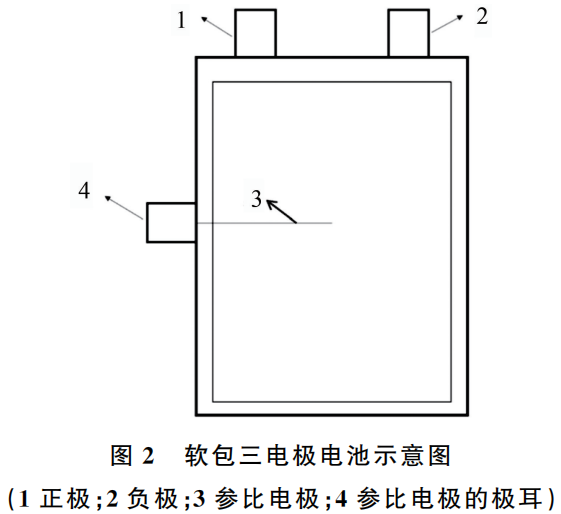
Figure 2: Schematic Diagram of a Pouch-type Three-electrode Cell
This schematic illustrates the internal layout and terminal configuration of a pouch cell specifically designed for three-electrode electrochemical analysis. Unlike standard two-electrode commercial cells, this setup includes an integrated reference electrode to decouple the cathode and anode potentials.
Detailed Component Breakdown of a three electrode pouch cell
Based on the numerical labels in the diagram:
Cathode (正极): The positive terminal of the battery, typically lead out from the top of the pouch.
Anode (负极): The negative terminal of the battery, paired with the cathode at the top.
Reference Electrode (参比电极): A thin, processed wire (such as the 40 $\mu m$ lithium-plated copper wire described previously) that is inserted into the cell stack. It is positioned between the cathode and anode layers, separated by membrane layers, to act as a stable voltage baseline.
Reference Electrode Tab (参比电极的极耳): The specialized terminal used to connect the internal reference electrode to the testing equipment (e.g., a potentiostat). As shown in the diagram, this tab is led out from the side of the pouch to avoid electrical interference with the main power tabs.
Key Design Features
Structural Integration: The cell utilizes a Z-fold stacking method, allowing the reference electrode (3) to be embedded precisely within the stack sequence (Cathode / Separator / Reference Electrode / Separator / Anode).
Versatile Positioning: While this diagram shows the reference tab (4) exiting from the side, the design allows for it to be led out from the top, sides, or bottom depending on the specific testing requirements.
Purpose: This configuration enables in-situ monitoring of individual electrode behaviors, which is critical for quantifying lithium plating and analyzing impedance changes during high-rate or low-temperature cycling.
1.3.3 Lithium Plating of the Reference Electrode
Using a coin cell charge-discharge testing equipment, the cells were taken after capacity grading (at 50% SOC). The reference electrode was then plated with lithium using the following methods:
(1) Forward Lithium Plating: The electrodes were connected as Cathode (+) and Reference Electrode (-). A current of 0.5 mA was applied for 2 hours.
(2) Reverse Lithium Plating: The electrodes were connected as Anode (-) and Reference Electrode (+). A current of 0.5 mA was applied for 2 hours.
1.4 Electrochemical Performance Testing of three electrode pouch cells
1.4.1 Rate Charging Performance Test
Rate charging performance tests were conducted on the three groups of pouch cells (A, B, and C) using power battery testing equipment at a charging rate of 1.5C and a temperature of 25 ± 2 °C. The test procedures were as follows: The cells were first charged at 0.3C constant current-constant voltage (CCCV) to 3.65 V, then discharged at 0.3C constant current (CC) to 2.5 V for 3 cycles. Finally, the cells were charged at a 1.5C rate to 3.65 V, with a 30-minute interval between each step. Simultaneously, a high-precision tester (HIOKI) was used to monitor the potential variations of the anode (vs. reference electrode).
1.4.2 Step Charging Test
Lithium iron phosphate (LFP) batteries are prone to lithium plating during low-temperature or high-rate charging. Consequently, in practical applications, a multi-step charging (step-charging) approach can be adopted: using a larger current at a low State of Charge (SOC) and reducing the current at a high SOC. This strategy minimizes the risk of lithium plating on the graphite anode toward the end of the charging process, ensuring overall battery performance. This study focuses on Group A, which poses the highest risk of lithium plating, using a step-charging sequence of 1.2C, 0.8C, and 0.3C at a test temperature of 25 ± 2 °C.
————–> Neware battery cyclers Neware cyclers and temp chamber all in one Neware 0~60℃ chamber
2. Results and Discussion
2.1 Material Characterization
Figure 3 displays the SEM images revealing the particle morphologies of the three graphite anode materials (A, B, and C). Both Groups A and B consist of a mixture of single crystals and secondary particles, with particle sizes ranging from 13 to 14 μm. In contrast, Group C is composed of small-sized single-crystal graphite with a particle size of 7 μm.
2.2 Battery Rate Charging Performance Test
As mentioned in the introduction, the introduction of a reference electrode allows for the monitoring of potential changes in both the cathode and anode during charging. Figure 4 shows the rate charging performance curves of the three groups of pouch cells (A, B, and C), and Table 2 provides the comparative data of the anode potentials at the end of the charging process.
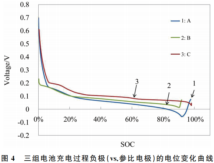
Comparing the charging curves of the three battery groups (A, B, and C), it is evident that Group C graphite anode material exhibits superior rate charging performance. From a material science perspective, small particle size and carbon coating treatments are conducive to enhancing the kinetic performance of graphite and reducing the risk of lithium plating on the anode. These test results are consistent with theoretical expectations.
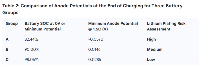
Research indicates that during the battery charging process, if the Li+ ions extracted from the cathode are not intercalated into the interior of the anode in a timely manner, the excess Li+ will be reduced on the anode surface. By introducing a reference electrode to monitor the actual potential of the anode during charging, a lithium plating risk can be determined if the minimum anode potential reaches 0V or below. Furthermore, a higher battery SOC at the point where the anode reaches 0V, or a higher minimum anode potential overall, indicates superior rate performance of the material.
2.3 Research on Battery Charging Protocols
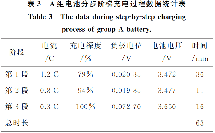
Group A batteries were selected for the multi-step charging study. The resulting curves are shown in Figure 5, and the statistical data from the step-charging process is summarized in Table 3.
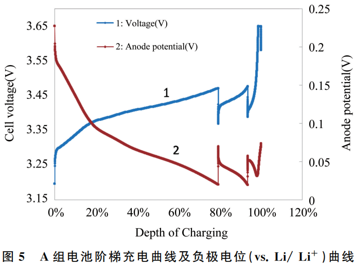
The data indicates that by employing a multi-step charging strategy with varying currents (1.2C, 0.8C, and 0.3C in sequence), the total charging duration is 63 minutes, which is essentially consistent with the time required for conventional 1C CC-CV (constant current-constant voltage) charging. At the end of the charging process, the anode potential is 0.0727 V, which remains above the lithium plating potential (0 V), thereby reducing the risk of anode lithium plating. Consequently, this charging method ensures both charging efficiency and battery performance without increasing the overall charging duration.
3. Conclusion
In this study, Lithium Iron Phosphate (LFP) pouch-type three-electrode cells were fabricated to qualitatively investigate the risk of lithium plating during the charging process. The results show that pouch cells utilizing different graphite anode materials exhibit varying risks of lithium plating at the end of charging. Specifically, graphite materials with small particle sizes and carbon coating demonstrate superior kinetic performance and a lower risk of lithium plating.
Research on the charging protocols for LFP batteries indicates that employing a multi-step charging strategy (with decreasing currents of 1.2C, 0.8C, and 0.3C) results in an anode potential of 0.07270 V at the end of charging. This value remains safely above the 0 V threshold, effectively mitigating the risk of anode lithium plating during the final stages of charge.
In summary, the three-electrode method provides significant guidance for studying lithium-ion battery charging regimes, evaluating the kinetic performance of graphite materials, selecting material systems, and conducting failure analysis of lithium-ion batteries.
Reference:
Gao Jiaoyang, Yuan Dongya, Ye Cuixia. Application of Three-Electrode Method in Performance Evaluation of Lithium-ion Batteries [J]. Battery Industry, 2022, 26(3):4.
文献参考:高娇阳, 袁东亚, 叶翠霞. 三电极方法在锂离子电池性能评价中的应用研究[J]. 电池工业, 2022, 26(3):4.
Due to the limited knowledge and English level is inevitable errors and omissions, if there are errors or infringement of the text, please contact me as soon as possible by private letter, I will immediately be corrected or deleted.