How to determine the charge/discharge cut off voltage of a lithium-ion battery? And what is charge/discharge cut off voltage?
What is charge/discharge cut off voltage?
The charge/discharge cutoff voltage refers to the upper and lower limits of the voltage set during the charging and discharging process of a lithium-ion battery to avoid battery damage, ensure safety, and extend its service life.

Charging Cut-off Voltage:
Definition: The highest voltage a battery is allowed to reach during charging. When the battery voltage reaches this value, the charging process must be stopped or switched to trickle charging/stop charging.
Purpose:
(1) Prevent overcharging: Continuing to charge beyond the cut-off voltage is called overcharging.
(2) Protect the positive electrode material: Excessively high voltage can cause irreversible structural changes in the positive electrode material (such as lithium cobalt oxide, lithium nickel cobalt manganese oxide, etc.) (such as lattice collapse, oxygen release), permanent capacity decay, and even thermal runaway (fire and explosion).
(3) Protect the negative electrode material: Excessively high voltage can cause lithium ions to over-intercalate on the surface of the negative electrode (usually graphite), and even cause metallic lithium to precipitate on the negative electrode surface (lithium plating), forming lithium dendrites. Lithium dendrites may pierce the separator, causing internal short circuits and serious safety accidents. Lithium plating also consumes active lithium ions, reducing capacity. (4) Preventing electrolyte decomposition: Under high voltage, the electrolyte is more prone to oxidative decomposition, producing gas (bulging) and byproducts, increasing internal resistance, and reducing performance and safety.
Typical values: Typically between 3.6V and 4.5V, depending on the battery’s positive electrode material:
- Lithium cobalt oxide: ~4.2V
- Ternary materials: ~4.2V or 4.35V (high voltage type)
- Lithium iron phosphate: ~3.6V – 3.65V
- Lithium manganese oxide: ~4.2V
Discharge Cut-off Voltage:
Definition: The lowest voltage a battery is allowed to reach during discharge. The discharge process must stop when the battery voltage drops to this value.
Purpose:
(1) Prevent over-discharge: Continuing to discharge below this voltage is called over-discharge.
(2) Protect the negative electrode current collector: During deep discharge, lithium ions are excessively extracted from the graphite negative electrode, and a low voltage can cause the negative electrode potential to rise. When the negative electrode potential rises to a certain level (usually corresponding to a battery voltage of approximately 2.5V-3.0V or below), the copper current collector of the negative electrode may begin to oxidize and dissolve. The dissolved copper ions may migrate to the positive electrode or deposit on the separator during subsequent charging, causing internal micro-short circuits and severely damaging battery performance and lifespan.
(3) Protect the positive electrode material: Some positive electrode materials may also experience structural damage during deep discharge. Preventing irreversible capacity loss: Over-discharge causes irreversible changes in the structure of the active material, and even recharging cannot restore all capacity.
(4) Prevent battery failure: Severe over-discharge can lead to complete battery failure, rendering the battery unusable for recharging. Typical values: Usually between 2.5V and 3.0V, depending on the battery chemistry, but the difference is smaller than that of the charging cutoff voltage. Common settings are 2.5V, 2.8V, or 3.0V.
Therefore, when setting the voltage range of the testing instrument, it is necessary to determine reasonable upper and lower limits based on the above principles and the specific chemical system of the positive/negative electrode materials to avoid overcharging or over-discharging during testing and ensure the validity and safety of the experiment.
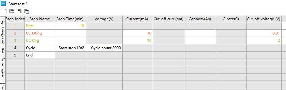
The following example demonstrates the cycle performance settings for a lithium-ion coin cell battery:
(1) Select the constant current cycling mode in the Neware BTS software.
(2) Test the assembled battery within the corresponding voltage range at a current density of 0.1 A/g. (Assume the active material mass is 0.1g and the test current is 10mA.)
(3) The positive electrode cutoff voltage range is determined based on the electrode material (e.g., the range for testing lithium iron phosphate/Li batteries can be set to 2~4.2V). The cutoff voltage can be obtained by consulting literature or testing polarization curves.
(4) For negative electrode materials, the battery generally undergoes a discharge step first, following the sequence of “rest – constant current discharge – constant current charging”. The input current is 10mA, the discharge cutoff voltage is 0.01V, the charging cutoff voltage is 2.0V, and the cycle count is set to 2000.
The test voltage range shown in the screenshot below is for reference only; the specific voltage range depends on the specific material.

Key Basis for Lithium-ion Battery Charge/Discharge Cut-off Voltage
Thermodynamic Stability (Chemical Stability) of Electrode Materials:
● Positive Electrode Material: When the charging voltage is too high, positive electrode materials (such as lithium cobalt oxide LiCoO₂, ternary materials NCM/NCA, lithium iron phosphate LiFePO₄, lithium manganese oxide LiMn₂O₄, etc.) may undergo irreversible structural phase transitions, lattice oxygen precipitation, transition metal ion dissolution, or violent oxidation side reactions with the electrolyte. This leads to capacity decay, increased internal resistance, and even thermal runaway.
● Negative Electrode Material: Primarily graphite. When the discharge voltage is too low (i.e., the negative electrode potential is too high), the graphite negative electrode may undergo excessive delithiation, leading to structural collapse (peeling, pulverization). More importantly, when the negative electrode potential is lower than the electrolyte’s reduction potential, the electrolyte will undergo continuous reduction decomposition on the negative electrode surface, generating an excessively thick solid electrolyte interface film or precipitating metallic lithium (lithium dendrites). Lithium dendrites can pierce the separator, causing a short circuit and leading to serious safety accidents.
● Electrolyte: The electrolyte (usually a mixture of organic carbonates containing lithium salts) has a stable electrochemical window. Exceeding the upper voltage limit will result in oxidation and decomposition at the positive electrode, while falling below the lower voltage limit will result in reduction and decomposition at the negative electrode. These side reactions consume active lithium and electrolyte, generate gas, damage the SEI film, and lead to performance degradation.
● Cycle Life: (1) While deep charge-discharge (i.e., using a wider voltage window) can achieve higher single-cycle capacity, it accelerates the aforementioned electrode material structure degradation and side reaction rates, significantly shortening the battery’s cycle life. (2) Setting a reasonable cutoff voltage to avoid prolonged operation of the battery at extreme potentials is a key strategy for extending battery life. For example, slightly increasing the discharge cutoff voltage (e.g., from 2.5V to 2.8V or 3.0V) or slightly decreasing the charge cutoff voltage (e.g., from 4.2V to 4.1V), although sacrificing a little capacity, can significantly increase the number of cycles.
Energy Density and Capacity: The battery’s energy density and release capacity are directly related to the charge-discharge voltage window. A wider voltage window means more lithium ions can be released, resulting in higher capacity and energy density.
Safety:
● Overcharging (exceeding the charging cut-off voltage) is one of the most dangerous situations for lithium-ion batteries. It easily leads to oxygen decomposition in the positive electrode material, heat generation from electrolyte oxidation and decomposition, and dendrite formation at the negative electrode, potentially causing thermal runaway, fire, or even explosion.
● Over-discharging (below the discharge cut-off voltage), while less dangerous, can cause copper current collectors to dissolve (at low potential). During subsequent charging, the dissolved copper ions may precipitate at the negative electrode, forming dendrites, which also poses a short circuit risk and severely damages battery performance. Strictly setting and adhering to the charge/discharge cut-off voltage is the first and most important line of defense for battery safety.
Application Scenarios and Requirements:
Different applications prioritize different battery performance requirements:
(1) Consumer Electronics (Mobile Phones, Laptops): High energy density and capacity are prioritized, typically allowing for a wider voltage window (e.g., 3.0V-4.2V or 3.0V-4.35V), with relatively moderate lifespan requirements.
(2) Electric Vehicles: High energy density, high power, long lifespan, and extremely high safety are required. Voltage windows are usually set more conservatively (e.g., 3.0V-4.2V for ternary lithium batteries, 2.5V-3.65V for lithium iron phosphate batteries), and BMS management is very strict.
(3) Energy Storage Systems: Long lifespan and cost are paramount. Very narrow voltage windows are typically used (e.g., lithium iron phosphate batteries operate between 3.0V and 3.4V, using only about 40% of the SOC range) to greatly extend cycle life.
Precisely setting and strictly controlling the charge/discharge cutoff voltage is the core foundation for ensuring the safe operation of lithium-ion batteries, optimizing cycle life, and balancing energy density and reliability. Whether developing novel electrode materials, optimizing electrolyte formulations, designing battery management system (BMS) strategies, or verifying battery performance under extreme conditions, precise, reliable, and highly repeatable testing and evaluation of batteries within strictly defined voltage windows and temperature environments are indispensable.
In actual battery R&D, production, and quality control, simulating battery charge-discharge behavior under different temperature conditions (high-temperature accelerated aging, low-temperature performance verification, room-temperature cycle life) and accurately capturing the battery state (such as capacity, internal resistance, temperature rise, coulombic efficiency, etc.) when the voltage reaches the cutoff limit is crucial for understanding material boundaries, optimizing process parameters, verifying BMS protection logic, predicting battery life, and assessing safety risks. Temperature, as a key variable affecting electrode reaction kinetics, interface stability, electrolyte transport, and side reaction rates, complements voltage management and together determines the overall performance and safety boundaries of the battery.
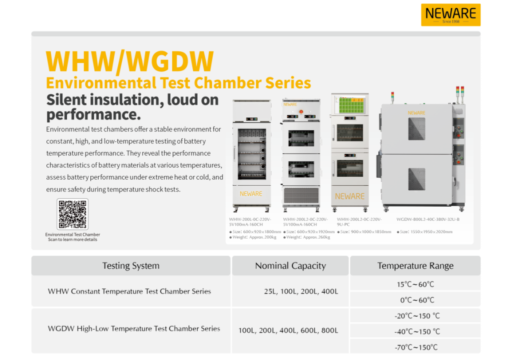
Neware all in one provides precise environmental control and testing solutions specifically for battery R&D and production. It integrates battery charge/discharge testing and an environmental test chamber, supporting battery performance testing under various temperature conditions.
● Highly integrated with charge/discharge testing modules and environmental simulation functions (such as constant temperature and high/low temperature), reducing floor space;
● Multiple battery testing functions, supporting constant current/constant voltage charge/discharge, capacity analysis, cycle life testing, DC internal resistance detection, etc.;
● Supports integrated operation of the BTS host computer control system, compatible with various battery testing equipment;
● Multi-temperature zone control scheme, enabling independent temperature control in multiple zones to meet complex testing needs;
● Multiple measurement ranges, supporting customized voltage and current, applicable to various testing scenarios such as materials research, 3C batteries, and power batteries.