
How to Properly Use Neware Prismatic Cell Fixtures: Operation and Commissioning Guide
Channel Wire Connection Methods
Connection Method with Adapter Cables (Figure 1)
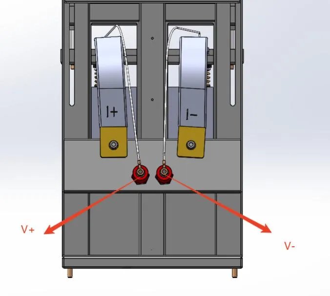
(1) For Prismatic Cell Fixtures rated over 150A, adapter cables are routed to the insulating posts at the rear of the Prismatic Cell Fixture and secured with fastening screws. The adapter cables are marked with identification ferrules/sleeves labeled I+, V+, V-, and I-.
Connection Method without Adapter Cables (Figure 2)
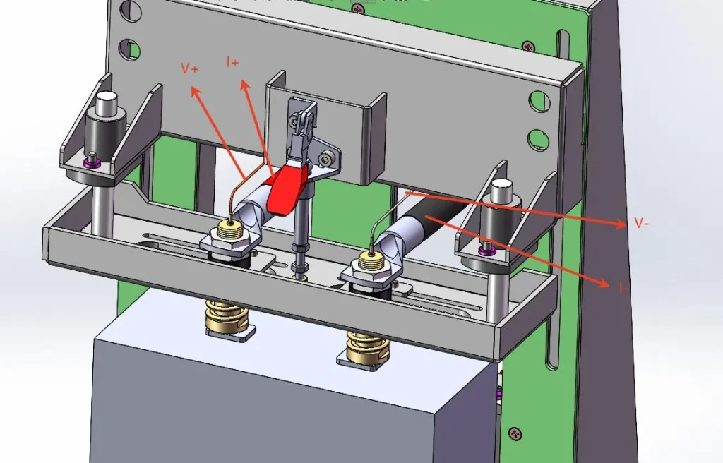
- For currents under 150A, channel wires connect directly to the probes, where V+ and I+ are connected to one probe, and V- and I- are connected to another probe.
- Red: Positive current wire; Orange: Positive voltage wire (refer to the identification ferrules).
(3) Black: Negative current wire; Gray: Negative voltage wire (refer to the identification ferrules).
Pre-Test Inspection of the Prismatic Cell Fixture
- Ensure all Prismatic Cell Fixture connection wires are reliable, screws are securely tightened, and soldering is firm.
- The probe surfaces must be clean with intact contact crowns/teeth. The voltage pins should compress and extend smoothly without sticking.
- The toggle clamp must move smoothly up and down, and the connection wires must not be twisted.
- The probe mounting plate must move up and down parallel to the baseplate.
- The height adjustment screws for compatibility must meet the requirements for secure locking.
Prismatic Cell Fixture Feature Identification
- The baseplate of the Prismatic Cell Fixture features a centerline aligned with the center of the probes.
- The left and right U-shaped markings on the Prismatic Cell Fixture are symmetrical, serving as a reference to center the battery on the Prismatic Cell Fixture baseplate.
- The probe spacing of the Prismatic Cell Fixture is horizontally adjustable (left and right).
- The probe mounting plate of the Prismatic Cell Fixture is vertically adjustable (up and down).
Prismatic Cell Fixture Commissioning Procedure
- Prepare a plastic straight ruler for commissioning (to prevent short circuits) with a measuring range exceeding the maximum dimensions of the battery.
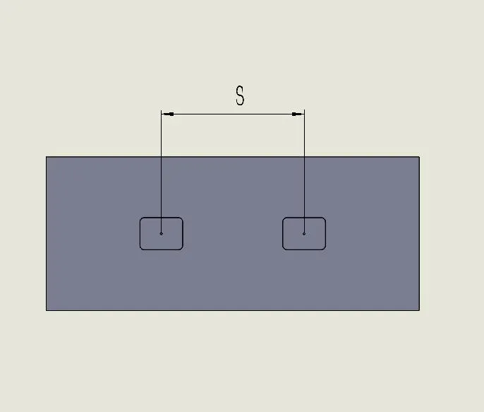
- Measure the inter-terminal spacing S of the battery (Figure 3).
- Loosen the probe fixing screws, adjust both the left and right probes to the S/2 position, and tighten the screws to secure them (Figure 4).
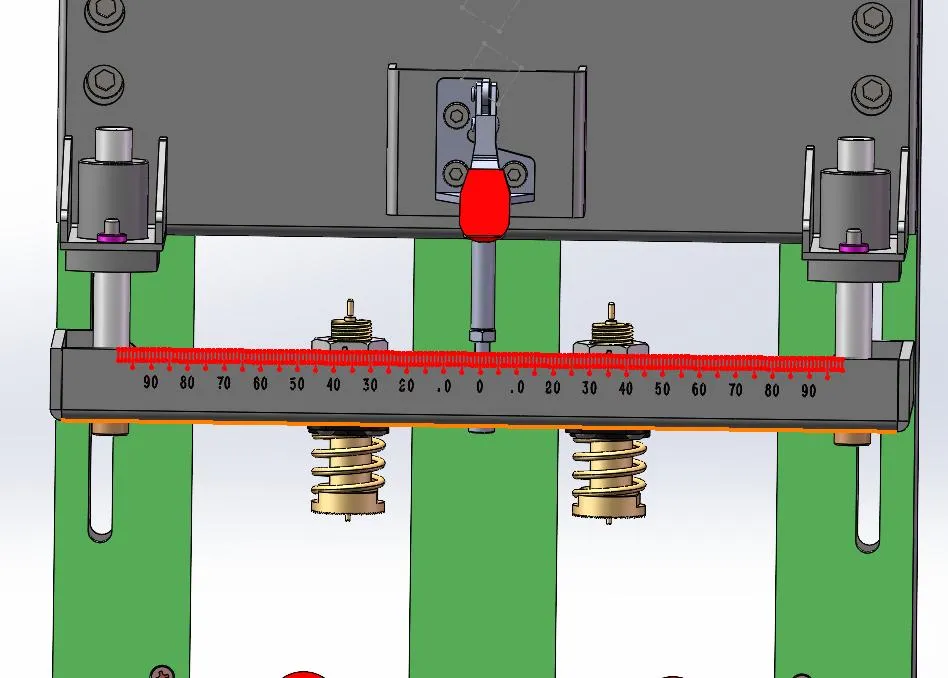
- Measure the battery height H (the dimension from the bottom to the terminal surface) (Figure 5).

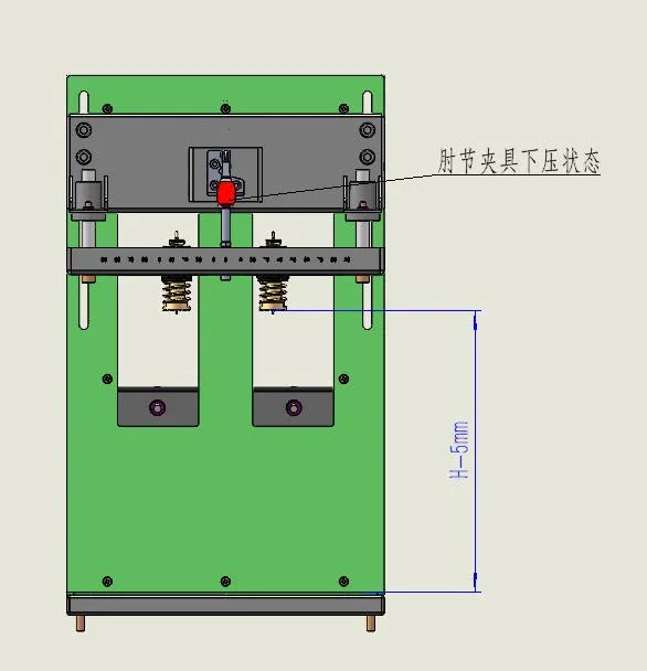
- Engage the toggle clamp to the lowered probe position. Loosen the fastening screws of the probe module, and adjust the height between the Prismatic Cell Fixture baseplate and the probe face (the contact teeth where the current end of the probe meets the battery terminal) to H – 5mm. Secure it with the fastening screws. Both the positive and negative probes must be set to a height of H – 5mm (with positive and negative probes kept at the same height) (Figure 6).
For more information on Neware prismatic cell fixtures and battery racks, please contact Neware.
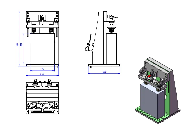
100A PTF-ZJ-F-100A-1CH-W230-H220 Prismatic Cell Fixture Drawings
Length / mm 80-230
Width / mm 20-80
Height / mm 80-220
Tab Center-to-Center Distance/mm 55-150
Adjustable and highly compatible, capable of accommodating battery testing across various sizes.
Please send us your maximum test current and battery size requirements, and we will match you with the ideal prismatic cell fixture and battery rack.
If the prismatic cell fixture is not used or commissioned properly, the following issues may occur during testing:
Short Circuits and Equipment Damage
Accidental Metal Contact: Measuring with metallic tools instead of an insulated plastic ruler can easily bridge the battery terminals, causing a direct manual short circuit.
Internal Fixture Shorting: Incorrect probe positioning or twisted and damaged cable insulation can cause internal short circuits, destroying the probes or test channels.
Overheating and Arcing (Damaged Probes or Battery Terminals)
Poor Contact or Insufficient Clamping Force: If the probe height is not adjusted strictly to H – 5mm, insufficient contact pressure will cause contact resistance to spike. Under high currents exceeding 100A, this leads to severe arcing, burning the battery terminals or probe contact teeth.
Loose Fastening Screws: Loose screws on adapter cables or channel wires increase local contact resistance, generating intense heat and posing a potential fire hazard.
Inaccurate Test Data and Misjudgment
Wiring Errors: Incorrectly connecting the current wires (I+/I-) and voltage wires (V+/V-) or failing to maintain reliable four-terminal (Kelvin) sensing prevents accurate voltage acquisition, leading to incorrect internal resistance (IR) readings, capacity errors, or fluctuating voltage samples.
Mechanical Damage or Uneven Stress on the Battery
Height or Alignment Offsets: If the probe plate is not parallel to the baseplate or the probes are not centered to S/2, the probe pressure can exert lateral force on the battery terminals, leading to terminal deformation, casing scratches, or seal damage that may trigger electrolyte leakage.
Mechanical Jamming and Wear
Stuck Toggle Clamps and Probes: Failing to inspect the probe springs and mechanisms can cause voltage pins to bind or move unevenly, leading to frequent channel dropouts and interrupted test runs.
For more information on Neware prismatic cell fixtures and battery racks, please contact Neware.